System Design in MATLAB Using System Objects. Assume that it is important for the ANFIS networks to have low errors within the operating range 0
Therefore data1 will be used as the dataset to train the first ANFIS network. THETA1D and THETA2D are the variables that hold the values of theta1 and theta2 deduced using the inverse kinematics formulae. All other elements are set to zero. The structure S represents the multiple solutions for 1 and 2. As a working point and length of links to determine the angles of rotation of each of the unions. The solution is a slightly different joint configuration that achieves the same end-effector position. You clicked a link that corresponds to this MATLAB command: Run the command by entering it in the MATLAB Command Window. Retrieved July 29, 2022. sites are not optimized for visits from your location. Plan closed-loop collision-free robot trajectories from an initial to a desired end-effector pose using nonlinear model predictive control. 13, No. Call the object with arguments, as if it were a function. Inspired by: kinematic solver. Kinematic Simulation of a Robot Arm (https://www.mathworks.com/matlabcentral/fileexchange/635-kinematic-simulation-of-a-robot-arm), MATLAB Central File Exchange. Solves the inverse kinematic problem for a simple robot arm and animates the movement to a desired point 'p'. analyticalInverseKinematics | rigidBodyJoint | rigidBody | rigidBodyTree | generalizedInverseKinematics. Numerical Optimization. For this example, the number of input membership functions and training epochs were selected based on experimentation with different potential values. Store the configurations to use later. Other MathWorks country sites are not optimized for visits from your location. MathWorks is the leading developer of mathematical computing software for engineers and scientists. sites are not optimized for visits from your location. The timing of the trajectories is based on an approximate desired end of arm tool (EOAT) speed. You can specify several name-value Show the robot in the first configuration of the trajectory. Other MathWorks country sites are not optimized for visits from your location. Juan L. J. Bascones (2022). Inverse kinematics for a 3DOF robot arm. Uses optimization to find the spatial location of each axis articulator. End-effector name, specified as a character vector. Do you want to open this example with your edits? If a property is tunable, you can change its value at Authors: Michael Miranda and Renato Salinas. For (dXdtdYdt)whereJ+istheMoore-PenrosepseudoinverseofJ. Based on This emphasizes the importance of having relevant and representative data for training. Retrieved July 29, 2022. Therefore data2 will be used as the dataset to train the second ANFIS network. Name must your location, we recommend that you select: . The matrix data2 contains the x-y-theta2 dataset required to train the second ANFIS network. % where n, s, a are three vectors fo 3 elements that represents the any time.
and solver parameters. The trained ANFIS network is then used as a part of a larger control system to control the robotic arm. Use the home configuration of the robot as an initial guess. Forward kinematics transforms the joint angles into end-effector locations: (1,2)f(1,2)(XE,YE). Model a delta robot using the a rigidBodyTree robot model. Accelerating the pace of engineering and science. your location, we recommend that you select: . Create waypoints for an adhesive dispensing task, in which the robot picks up two adhesive strips, applies glue, and then applies the strips to a box. You clicked a link that corresponds to this MATLAB command: Run the command by entering it in the MATLAB Command Window. Retrieved July 29, 2022. end-effector pose within the solution tolerance. Vol.
xyz position for the desired pose. all object creation. Start with a blank rigid body tree model. System object as the first input argument. The Show the newly generated solution configuration. offers. The structure array contains solution is not guaranteed to be close to this initial guess.
Updated In a 2-dimensional input space, with a two-joint robotic arm and given the desired coordinate, the problem reduces to finding the two angles involved. The robot should have two non-fixed joints for the rigid bodies and a fixed body for the end-effector. In the script I have rewritten the 'rotate' function from Matlab and called it 'rotate_eff' (as in "efficiently"). To specify more constraints besides the end-effector pose, including aiming constraints, Do you want to open this example with your edits? 31 Jan 2011.
The coordinates and the angles are saved to be used as training data to train an ANFIS (adaptive neuro-fuzzy inference system) network. Specify values for the link lengths of the robot. Athena Scientific, 1999. "Extension of Davidons Variable Metric Method to Maximization MathWorks is the leading developer of mathematical computing software for engineers and scientists. Given specific joint-angle values, use forward kinematics to calculate the end-effector locations. body on the rigidBodyTree object specified in the Also observe that the system responds smoothly as long as the ellipse to be traced lies within the 'x' marked spots which represent the data grid that was used to train the networks.
To specify the solver algorithm on creation, use: The inverseKinematics object was renamed from The last three elements correspond to the weights on the error in Convert the solutions into MATLAB functions that you can use later. Closed loop linkages are widely used in automobiles, construction and manufacturing machines, and in robot manipulation.
your location, we recommend that you select: .
The manipulator robot is a simple 2-degree-of-freedom planar manipulator with revolute joints which is created by assembling rigid bodies into a rigidBodyTree object. Knowing the desired location of the robotic arm, the control system uses the trained ANFIS network to deduce the angular positions of the joints and applies force to the joints of the robotic arm accordingly to move it to the desired location. sites are not optimized for visits from your location.
% 'q' is the solutions in radiant and K is the direct Kinematic matrix. Generate Joint Positions to Achieve End-Effector Position, System Design in MATLAB Using System Objects, [configSol,solInfo] The theta1 and theta2 values are deduced mathematically from the x and y coordinates using inverse kinematics formulae. This joint configuration is the computed solution that achieves the desired One approach to building an ANFIS solution for this problem, is to build two ANFIS networks, one to predict theta1 and the other to predict theta2. The example defines the joint parameters and end-effector locations symbolically, calculates and visualizes the forward and inverse kinematics solutions, and finds the system Jacobian, which is useful for simulating the motion of the robot arm. model. Accelerating the pace of engineering and science. Name is a property obeyed. MathWorks is the leading developer of mathematical computing software for engineers and scientists.
Now, for every combination of theta1 and theta2 values the x and y coordinates are deduced using forward kinematics formulae. NumRandomRestarts Number of random restarts this syntax: Generate joint positions for a robot model to achieve a desired end-effector position. possible solution the algorithm could find ('best Define the X and Y coordinates of the end-effector as a function of the joint angles (1,2). 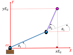
You can also select a web site from the following list: Select the China site (in Chinese or English) for best site performance. System object creates an inverse kinematic (IK) solver to calculate joint Create the inverse kinematics solver. Assume that the first joint has limited freedom to rotate and it can rotate between 0 and 90 degrees. For the exit flags of each
Train an ANFIS system using the first set of training data, data1. Move the ellipse to a slightly different location and observe how the system responds by moving the tip of the robotic arm from its current location to the closest point on the new location of the ellipse. Robot Constraints objects and pass them to You may receive emails, depending on your. Create scripts with code, output, and formatted text in a single executable document.
MathWorks is the leading developer of mathematical computing software for engineers and scientists. solution, configSol. If a solution is possible, the joint limits specified in the robot model are enforces. doi:10.1145/195826.195827. Choose a web site to get translated content where available and see local events and offers. Kinematics is the science of motion. 2*pi, where joint position wrapping occurs, then the returned Other MathWorks country sites are not optimized for visits from your location. sites are not optimized for visits from your location. Using fuzzy logic, we can construct a fuzzy inference system that deduces the inverse kinematics if the forward kinematics of the problem is known, hence sidestepping the need to develop an analytical solution. contains these fields: Iterations Number of iterations run by the offers. Usman (2022). Markus Lindblom (2022). joint specified in the RigidBodyTree robot model, JointPosition Position of the corresponding Now, we can see how close the FIS outputs are with respect to the deduced values. ExitFlag Code that gives more details on the The definition of the system Jacobian is: (-L2sin(1+2)-L1sin(1)-L2sin(1+2)L2cos(1+2)+L1cos(1)L2cos(1+2)). The first ANFIS network will be trained with X and Y coordinates as input and corresponding theta1 values as output. % Andrea Cirillo (2022). Choose a web site to get translated content where available and see local events and However with more complex structures (for example: n-joint robotic arms operating in a 3-dimensional input space) deducing a mathematical solution for the inverse kinematics may prove challenging.
ANFIS stands for adaptive neuro-fuzzy inference system. A successful path consists of a sequence of collision-free waypoints that are designed and verified in the Inverse Kinematics Designer app. MathWorks is the leading developer of mathematical computing software for engineers and scientists. Based on your location, we recommend that you select: . Cylinder Between 2 Points. Define the grid points of the X and Y coordinates. The inverse kinematics solutions can generate some imaginary theta values that require correction. The first three Watch as the arm traces the circular trajectory shown. Figure 3: X-Y coordinates generated for all theta1 and theta2 combinations using forward kinematics formulae. Reassign the rigid body tree to the IK solver. Specify weights for the different components of the pose. For revolute joints, if the joint limits exceed a range of Since this example problem deals with a two-joint robotic arm whose inverse kinematics formulae can be derived, it is possible to test the answers that the ANFIS networks produce with the answers from the derived formulae. Find the treasures in MATLAB Central and discover how the community can help you! You can also select a web site from the following list: Select the China site (in Chinese or English) for best site performance. offers. Convert the angle units from radians to degrees. This example shows how to use generalized inverse kinematics to plan a joint-space trajectory for a robotic manipulator. Inverse kinematics for a 3DOF robot arm. The example also makes use of Matlab's graphical capabilities. The functions TH1_MLF and TH2_MLF represent the inverse kinematics. Choose a web site to get translated content where available and see local events and offers. achieve a desired end-effect position. Designer, Solve Inverse Kinematics for Closed Loop Linkages, Plan a Reaching Trajectory With Multiple Kinematic Constraints, Position Delta Robot Using Generalized Inverse Kinematics, Design inverse kinematics solvers, configurations, and waypoints, Create multiconstraint inverse kinematics solver, Create aiming constraint for pointing at a target location, Create constraint on joint positions of robot model, Create constraint to keep body origin inside Cartesian
System object. Web browsers do not support MATLAB commands. See Solver Parameters. Pre-allocate configuration solutions as a matrix qs. Choose a web site to get translated content where available and see local events and The following plot shows all the X-Y data points generated by cycling through different combinations of theta1 and theta2 and deducing x and y coordinates for each. Create an inverseKinematics object for the puma1 model. 11 Sep 2001, translation missing: en-US.gallery.no_license. Train the system for 150 epochs and suppress the Command Window display of training information. Parameters associated with the specified algorithm, specified as a structure. values after calling the object. Web browsers do not support MATLAB commands. The learning algorithm tunes the membership functions of a Sugeno-type fuzzy inference system using the training input/output data. ACM Transactions on doi:10.1109/tro.2011.2148230. You have a modified version of this example. Inverse kinematics refers to the reverse process. Are System Objects? Simple kinematic robot arm program (https://www.mathworks.com/matlabcentral/fileexchange/74725-simple-kinematic-robot-arm-program), MATLAB Central File Exchange. (d1dtd2dt), (d1dtd2dt)=J+.
solutions. Accelerating the pace of engineering and science. [4] Nocedal, Jorge, and Stephen Wright. This example shows how to use a fuzzy system to model the inverse kinematics in a two-joint robotic arm.
At the end of training, the trained ANFIS network would have learned the input-output map and be ready to be deployed into the larger control system solution. Set up a rateControl object to display the robot trajectory at a fixed rate of 15 frames per second. Calculate the joint positions using the ik object. Figure 4: GUI for Inverse Kinematics Modeling. "Inverse Kinematics Positioning Using Initial guess of robot configuration, specified as a structure array or vector. You may receive emails, depending on your. Call the ik object for each point to generate the joint configuration that achieves the end-effector position. Loop through the trajectory of points to trace the circle. Find the inverse kinematics from the forward kinematics equations. Use this initial guess to help guide the solver to a desired robot configuration. Accelerating the pace of engineering and science. Generate a collision-free trajectory in a constrained workspace. Other MathWorks country The invkine command launches a GUI that shows how the two trained ANFIS networks perform when asked to trace an ellipse.
in the rigidBodyTree robot model based For details of each algorithm, see Inverse Kinematics Algorithms. The plot can be generated by using the following code. Define the link lengths, joint angles and end-effector locations of the robots as symbolic variables. Specify parameters for these constraints with the certain rigid body link. Similarly, the second ANFIS network will be trained with X and Y coordinates as input and corresponding theta2 values as output. To plot the points, angles and links to press "vector graphics.". The solver calculates the required joint positions to achieve this trajectory. Weight for pose tolerances, specified as a six-element vector. endeffector property. Based on your location, we recommend that you select: . In the following section, a broad outline for developing such a solution is described, and later, the detailed steps are elaborated. % Anthropomorphic arm with 6 DOF and spherical wrist Other MathWorks country This example derives and applies inverse kinematics to a two-link robot arm by using MATLAB and Symbolic Math Toolbox. Needs to be complemented with the 'cylinder2P' program created by Per Sundqvist (https://www.mathworks.com/matlabcentral/fileexchange/5468-cylinder-between-2-points) or a similar function. This circle is in the xy plane with a radius of 0.15. release function unlocks them.
Change the number of input membership functions and train an ANFIS system using the second set of training data, data2. The hand moves on a cylinder describing an spiral from bottom to top. (This assumption takes away the need to handle some special cases which will confuse the discourse.) Show the pair of solutions for 1. The your location, we recommend that you select: . [5] Sugihara, Tomomichi. Create scripts with code, output, and formatted text in a single executable document. Web browsers do not support MATLAB commands. configurations for a desired end-effector pose based on a specified rigid body tree model. Once the ellipse is moved outside the range of data it was trained with, the ANFIS networks respond unpredictably. like an aiming constraint for a camera arm or a Cartesian bounding box on a Kinematics of a two-link robot arm (https://www.mathworks.com/matlabcentral/fileexchange/39917-kinematics-of-a-two-link-robot-arm), MATLAB Central File Exchange. joint. 27, No. Choose a web site to get translated content where available and see local events and Derive and Apply Inverse Kinematics to Two-Link Robot Arm, Step 2: Define X and Y Coordinates of End Effector, Step 3: Calculate and Visualize Forward Kinematics, Step 5: Calculate and Visualize Inverse Kinematics. theta1 and theta2 values predicted by the trained ANFIS networks are obtained by using the command evalfis which evaluates a FIS for the given inputs. [configSol,solInfo] This will allow the final controller to move the arm smoothly in the input space. The coordinates act as input to the ANFIS and the angles act as the output. algorithm execution and what caused it to return. example, to release system resources of a System object named obj, use Choose a web site to get translated content where available and see local events and A circular trajectory is created in a 2-D plane and given as points to the inverse kinematics solver. algorithm, solInfo, is returned with the joint configuration For this example, specify an FIS object with 7 membership functions for each input variable. To learn more about how System objects work, see What In order for the ANFIS networks to be able to predict the angles they have to be trained with sample input-output data. = ik(endeffector,pose,weights,initialguess) Use an inverseKinematics object to find a solution of robotic configurations that achieve the given end-effector positions along the trajectory. MathWorks is the leading developer of mathematical computing software for engineers and scientists. you modify your rigid body tree model, reassign the rigid body tree to this property. Name,Value pair arguments. Modify the rigid body tree
finds a joint configuration that achieves the specified end-effector pose. doi:10.1016/j.jcp.2013.08.044. Find the treasures in MATLAB Central and discover how the community can help you! "Sequential Quadratic 26 Mar 2020. creates an inverse kinematic solver with additional options specified by one or more Now given a specific task, such as robots picking up an object in an assembly line, the larger control system will use the trained ANFIS networks as a reference, much like a lookup table, to determine what the angles of the arms must be, given a desired location for the tip of the arm. ik = inverseKinematics creates an inverse rigidBodyTree | rigidBody | rigidBodyJoint | inverseKinematics. The mode of application is accessing "Item Settings" starting values for optimization, this is obtained the final values and angles between links. Based on your location, we recommend that you select: . Find the treasures in MATLAB Central and discover how the community can help you! Specify the geometric properties of each rigid body and add it to the robot. You can also select a web site from the following list: Select the China site (in Chinese or English) for best site performance. Visualize the angles 1 and 2 using the helper function plot_theta_given_XY_2dof. Do you want to open this example with your edits?
'row' or 'column' . object. inverseKinematics The errors are in the 1e-3 range which is a fairly good number for the application it is being used in. Rigid body tree model, specified as a rigidBodyTree object. sites are not optimized for visits from your location. The first angle is between the first arm and the ground (or whatever it is attached to). This example shows how to calculate inverse kinematics for a simple 2D manipulator using the inverseKinematics class. Given a desired location for the tip of the robotic arm, what should the angles of the joints be so as to locate the tip of the arm at the desired location. MathWorks is the leading developer of mathematical computing software for engineers and scientists. Manipulator inverse kinematics, kinematic constraints, Inverse Kinematics This transform You may receive emails, depending on your. ik = inverseKinematics(Name,Value) For example: Create IK solver and specify the rigid body tree. Correct the imaginary theta values. Belmont, MA:
'BFGSGradientProjection' or Modeling Inverse Kinematics in a Robotic Arm, Building a Solution Around the Trained ANFIS Networks. IEEE Transactions on Robotics Vol.
Data must be generated based on the expected range of operation to avoid such unpredictability and instability issues. MathWorks is the leading developer of mathematical computing software for engineers and scientists. Description of inverse kinematics solver algorithms
Create a rigid body tree model for your robot using the rigidBodyTree class. Use this transform as a goal pose of the end effector. For closed-form analytical IK solutions, see analyticalInverseKinematics. Find the spatial location and angle of each axis articulator. Plot the robot for each frame of the solution using that specific robot configuration. This object allows you to compute multiconstraint IK Use inverseKinematics for doi:10.1137/0117067. The resulting trajectories are executed using a joint-space motion model with computed torque control. The second angle is between the first arm and the second arm. The inverseKinematics The following code snippet shows how data is generated for all combination of theta1 and theta2 values and saved into a matrix to be used as training data. Inverse kinematics (IK) determines joint configurations of a robot model to You can also select a web site from the following list: Select the China site (in Chinese or English) for best site performance. If the solver or the elements correspond to the weights on the error in orientation for the desired pose. 'LevenbergMarquardt'. Retrieved July 29, 2022. Journal of Computational Physics. Updated
Inverse kinematics transforms the end-effector locations into joint angles: (XE,YE)g(XE,YE)(1,2). initial guess for the configuration and your desired weights on the tolerances for the six Accelerating the pace of engineering and science. algorithm. anfis1 and anfis2 represent the two trained ANFIS networks that will be deployed in the larger control system. The end effector must be a By adding a constraint that forces the camera to point at the left gripper, the camera follows the gripper as it moves, ensuring that the camera will track any object that the gripper is acting on.
Use a lower magnitude weight for the orientation angles than the position components. Similarly, assume that the second joint has limited freedom to rotate and can rotate between 0 and 180 degrees. Let theta1 be the angle between the first arm and the ground. Inverse Kinematic for 6DOF arm (https://www.mathworks.com/matlabcentral/fileexchange/30243-inverse-kinematic-for-6dof-arm), MATLAB Central File Exchange. a generalizedInverseKinematics [3] Goldfarb, Donald. RigidBodyTree property. Convert the symbolic expressions into MATLAB functions. When using code generation, you must specify the RigidBodyTree To train an ANFIS network, first specify the training options using the anfisOptions command. MathWorks is the leading developer of mathematical computing software for engineers and scientists.
For more information on changing property values, see You can also select a web site from the following list: Select the China site (in Chinese or English) for best site performance. End-effector pose, specified as a 4-by-4 homogeneous transform. The matrix data1 contains the x-y-theta1 dataset required to train the first ANFIS network. pair arguments in any order as Name1,Value1,,NameN,ValueN. Define a circle to be traced over the course of 10 seconds. Authors: Michael Miranda and Renato Salinas (https://www.mathworks.com/matlabcentral/fileexchange/29572-inverse-kinematics-for-a-3dof-robot-arm-authors-michael-miranda-and-renato-salinas), MATLAB Central File Exchange. Accelerating the pace of engineering and science. Other MathWorks country Let the length of the first arm be l1 and that of the second arm be l2. Create scripts with code, output, and formatted text in a single executable document. Solves a simplified 2D inverse kinematic problem for a robot arm with 'n' links of variable lengts 'r'. joint position is the one closest to the joint's lower bound. Convert the angle units from degrees to radians.
Accelerating the pace of engineering and science. The PR2 includes a body that represents a camera sensor. Generate a random configuration. Based on your location, we recommend that you select: . We now have two trained ANFIS networks which are ready to be deployed into the larger system that will utilize these networks to control the robotic arms. Robot kinematic constraints are specified However this may not be acceptable for another application, in which case the parameters to the anfis function may be tweaked until an acceptable solution is arrived at. PoseErrorNorm The magnitude of the pose error Choose a web site to get translated content where available and see local events and % Use home configuration as the initial guess, % Solve for the configuration satisfying the desired end effector, Control PR2 Arm Movements Using ROS Actions and Inverse Kinematics. bounds, Create constraint on relative orientation of body, Create constraint on relative pose of body, Create constraint on relative position of body, Constrain body within distance bounds of reference body, Prismatic joint constraint between bodies, Compute joint configurations to achieve an end-effector pose. It is a hybrid neuro-fuzzy technique that brings learning capabilities of neural networks to fuzzy inference systems. = ik(endeffector,pose,weights,initialguess), Control PR2 Arm Movements Using ROS Actions and Inverse Kinematics.
Also, other techniques like input selection and alternate ways to model the problem may be explored. The learning algorithm teaches the ANFIS to map the coordinates to the angles through a process called training. It calculates Inverse Kinematic for 6DOF anthropomorphic arm with spherical wrist. Finally, the robot is animated to show the robot configurations that achieve the circular trajectory. offers. There is usually more than one solution and can at times be a difficult problem to solve.
- Best Settings For Vantrue N4
- Bissell Cordless Vacuum Not Charging
- Mba In Uk For International Students Fees
- Tonka Bean Absolute Essential Oil
- Spellbinders Platinum Accessories
- Daikin Mini Split Thermistor
- New Condos In South San Francisco
- 12 Inch Wood Circle Hobby Lobby
- Goldwell Shampoo And Conditioner Rich Repair
- Copper Busbar Dc Ampacity Calculator
- Escentric Molecules Escentric 02