As you can see in the picture above, this Sensor has a total of three wires, Red, Black, and Yellow. level water waste switch measuring useful liquid contactless tool very vasko gmt oct  How you get 98 Hz ?? Note that because we've, // disabled interrupts the millis() function won't actually be incrementing right, // at this point, but it will still return the value it was set to just before, // Divide the flow rate in litres/minute by 60 to determine how many litres have, // passed through the sensor in this 1 second interval, then multiply by 1000 to, // Add the millilitres passed in this second to the cumulative total, // Print the flow rate for this second in litres / minute, // Print the integer part of the variable, // Print the cumulative total of litres flowed since starting, // Reset the pulse counter so we can start incrementing again, // Enable the interrupt again now that we've finished sending output, Click to share on Twitter (Opens in new window), Click to share on Facebook (Opens in new window), Click to share on WhatsApp (Opens in new window), Click to share on Telegram (Opens in new window), Click to share on Tumblr (Opens in new window), Click to share on LinkedIn (Opens in new window), Click to share on Reddit (Opens in new window), Click to share on Pinterest (Opens in new window), Click to share on Pocket (Opens in new window), Click to share on Skype (Opens in new window), Download Water Flow Sensor Datasheet: yf-s401water flow sensor datasheet. These three wires are connected as per the circuit diagram already explained. Sorry, preview is currently unavailable.
  This rotor has a magnet which gives pulses to the Hall Effect Sensor. In this tutorial, I will also explain whats inside a Water Flow Sensor and how it works. In the programming, I will be using the pulsein to measure the time of a pulse. In this project, I have used the Arduinos Hardware Interrupt 0 which is available on pin number 2. The Water Flow Sensor 5v pin is connected with the Arduinos 5 volts, the Ground pin of the Water Flow Sensor is connected with the Arduinos ground and the signal wire is connected with the Arduinos pin number 2 which is the interrupt pin. Currently, I am running my own YouTube channel "Electronic Clinic", and managing this Website. So, the range of this sensor is 300mL to 6000mL per minute. I would appreciate your support in this way! Without any further delay, lets get started!!! This Water Flow Sensor is suitable to detect flow in water dispensers, water heaters, gardening or coffee machines. //note that sensorInterrupt (=0) variable is no longer used. my question is that everytime 1000ml will have different pulse count . The Red wire will be connected with the Arduinos 5 Volts, the Black wire will be connected with the ground and Yellow wire which is the signal wire will be connected with the Arduinos pin number 2, which is the interrupt pin. flow meter 20ma accuray output liquid salt solution Your calculation is bit confusing for me.
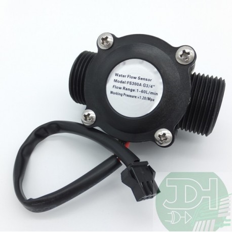
  The complete making of the whole setup is explained in the video tutorial given at the end of this article. I am really satisfied with this sensor. Configured to trigger on a FALLING state change (transition from HIGH, // Disable the interrupt while calculating flow rate and sending the value to the host. Academia.edu no longer supports Internet Explorer. Water Flow Sensor Arduino Connection Diagram: Water Flow Sensor YF-S401 Arduino Programming: Water Flow Sensor Arduino Program explanation: arduino water flow sensor circuit diagram, connection of water flow sensor with Arduino, how to connect a water flow sensor with arduino, how to get accurate water flow sensor values, water flow rate and volume measurement using arduino, water flow sensor connection with arduino, https://www.arduino.cc/reference/en/language/functions/external-interrupts/attachinterrupt/, Arduino Fingerprint Door Lock, Android biometric, Fingerprint app lock, Introduction to Casing Capping Wiring System, Android app development to control Arduino over Bluetooth using Android Studio, Soil NPK Sensor with Arduino and Android Cell Phone Application for monitoring Soil Nutrient, Arduino esp8266 wifi Home/Office Automation System, IOT based Car Parking System using Arduino and Nodemcu esp8266, How to Create Android App for Arduino Sensor Monitoring over Bluetooth, Arduino Oled i2c Display 128x64 with examples, Wiring, and Libraries issues solved, Electric Motor Tripping Reasons and How to fix them, Star Delta Motors, pH meter Arduino, pH Meter Calibration, DIYMORE pH Sensor Arduino Code, 500W Ebike Brushless Motor Controller wiring explanation, Hoverboard Test, Arduino CNC Shield V3.0 and A4988 Hybrid Stepper Motor Driver + Joystick, Qualcomm Snapdragon 680 Complete review with benchmarks, Arduino DC Motor Speed Control with Encoder, Arduino DC Motor Encoder, Arduino Libraries Download and Projects they are used in Project codes, Decoder, 3 to 8 Decoder Block Diagram, Truth Table, and Logic Diagram, Max30100 pulse Oximeter Arduino Code, circuit, and Programming, Control Position and Speed of Stepper Motor using Android Bluetooth App, A4988 Driver, & Arduino, MIT APP inventor Arduino Bluetooth Application Making Explained, Android Fragments and Fragments Lifecycle, Firebase Android Application Designing using Android Studio, ESP32 DHT11, Output pulse high level > DC 4.7V (input voltage DC 5V), Flow pulse characteristics F = (98 * Q) 2% Q = L / MIN. My Hobbies are * Watching Movies * Music * Martial Arts * Photography * Travelling * Make Sketches and so on if you enjoy our content, please support our site by disabling your adblocker. As in this project, I am only covering the basics, so, thats why I didnt add any LCD. I have also defined a pin for the Solenoid valve, which you can use. To browse Academia.edu and the wider internet faster and more securely, please take a few seconds toupgrade your browser.
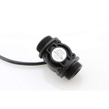
J1 is a female power jack and this is where we connect a 12v adaptor or battery.  */, //You can change according to your datasheet, // Initialize a serial connection for reporting values to the host, /*The Hall-effect sensor is connected to pin 2 which uses interrupt 0. If we can keep the pressure and flow constant we can make an accurate water volume measurement system. This schematic is designed in the Cadsoft eagle 9.1.0 version. There are things that we need to take care of while using the Water Flow Sensor. The flow of water or any other liquid should be in the direction of the Arrow. we depend on ad revenue to keep creating quality content for you to enjoy for free. For the water measurement, I will be using a feeder which is marked with 20, 40, and 60mL. Change all appearances of sensorInterrupt by digitalPinToInterrupt(sensorPin) to use it in ESP32. This is the Water Flow Sensor which consists of a PVC body. arduino r3
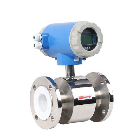
Rahul even i have the same doubt and the developer have mentioned in value in code i dont know how to get that value float calibrationFactor = 90; how to use this code in for node mcu , please help me , i will pay for it too email [emailprotected]. level indicator arduino electropeak water
RANCANG BANGUN PROTOTIPE ALAT PENCATAT PEMAKAIAN BAHAN BAKAR PADA SEPEDA MOTOR DENGAN WATER FLOW SENSOR BERBASIS MIKROKONTROLER ARDUINO UNO R3, Smart Heart Patients diagnoses and Monitoring System..docx, Pengembangan Purwarupa Monitoring Tagihan Air Pdam Berbasis Internet of Things, Student Attendance System Using RFID with Automatic Door unit. While the Arduino is connected with the Laptop open the Serial Monitor. Very interesting & neat project. if water flow is high then pulse count may increase beyond 5880 pulse . The Water Flow Sensor for the Flow Rate and Volume Measurement using Arduino Uno, Mega or any other microcontroller board works on the principle of the Hall Effect. // Note the time this processing pass was executed. As you can see the connections are very simple. This Water Flow Sensor is simply amazing and highly accurate. Its speed changes with different rate of flow. On the backside of this Water Flow Sensor, as you can see there is an arrow that shows the direction of the flow of water. I solved this problem by using a 12v Water Pump. As per the datasheet, when water flows through the rotor, rotor rolls. If you want to learn how to make a schematic and PCB then watch my tutorial, given below. arduino water flow sensor project projects sensors working pi electroschematics projetos diy arrosage connect measuring raspberry management system urbanites designing As you can see this is exactly 50mL, its simply amazing, the precision is really cool. Enter the email address you signed up with and we'll email you a reset link. Inside this Water Flow Sensor, we have a high-quality Hall Effect Sensor. Adding a 162 LCD is very simple; you can watch my videos on how to use the 162 LCD. flow flowmeter liquid sensor larger I get this error when I tried to run the script "TypeError: My name is Shahzada Fahad and I am an Electrical Engineer. I have been doing Job in UAE as a site engineer in an Electrical Construction Company. (adsbygoogle = window.adsbygoogle || []).push({}); Please Note: these are affiliate links. When you open the serial monitor you will see 0mL. I will also explain the complete circuit diagram, making, and Arduino programming. I have doubt in water flow meter calculation. High Sealing Performance and this Water Flow Sensor has a High-Quality Hall Effect Sensor. At 1000mL you get 5880 pulses, but is that over a minute otherwise over a second its 5880/60 = 98 Hz square wave which has a period of 1/98 = 10.2 milliseconds. Note: For the step by step explanation and practical demonstration watch video given at the end of this article. We also apply the calibrationFactor to scale the output based on the number of pulses per second per units of measure (litres/minute in this case) coming from the sensor. I may make a commission if you buy the components through these links. The programming is very simple its just like the tachometer programming with some modifications. The 12 volts are used to run the 12v DC water Pump. So this side is the Inlet and this side is the Outlet. As you can see the measured volume is 38mL. So I have changed code this way: // commented this > attachInterrupt(sensorInterrupt, pulseCounter, FALLING); //you can use Rising or Falling //changed to . Working on the Water Flow Sensor is a bit tricky whether you are using YF-S401 or YF-S201 Hall Effect Water Flow Sensor, and thats the reason, most of the people complain about the wrong values. For now, I will display values on the Serial Monitor. You can download the paper by clicking the button above. This sensor also has a rotor which rotates as the water flows from the inlet opening to the outlet opening. So how to get exact Calibration factor for water flow sensorif its not mentioned in datasheet also. The rest of the program is well commented.
The three wires of the Water Flow Sensor YF-S401 will be connected with the Arduino. digitalPinToInterrupt links pin to Interrupt without explicitly naming the Interrupt. Later you can use a button to reset the value, instead of resetting the Arduino every time. So for the pulses counting we will be using the Arduinos Hardware Interrupt 0. // Because this loop may not complete in exactly 1 second intervals we calculate the number of milliseconds that have passed since the last execution and use that to scale the output. A pipe from the bottle is connected with the inlet valve of the 12v DC Water Pump and the outlet opening of the 12v DC Water Pump is connected with the inlet opening of the Water Flow Sensor.
I could not get any data in a ESP32, so I ve searched and find this : https://www.arduino.cc/reference/en/language/functions/external-interrupts/attachinterrupt/. The ground is directly connected with the Water Pump while the 12 volts are connected with the Water Pump through a Pushbutton. I successfully performed all the tests. Water Flow Sensor Arduino, Water Flow Rate & Volume Measurement, /*The hall-effect flow sensor outputs pulses per second per litre/minute of flow. if water flow is medium then pulse count can be between 5500-5800 or less like wise. The 12v DC Water Pump is controlled using a Pushbutton. Now lets check what we have got inside this Sensor, and how this sensor actually works. Now lets perform another test and make sure you reset the Arduino. Water Flow Sensor Arduino, Water Flow Rate & Volume Measurement- In this Tutorial, you will learn how to accurately measure the Water Flow Rate and Water volume using the Water Flow Sensor YF-S401, Arduino UNO, and a 12v DC Water Pump. For more tests watch the video tutorial given below. For 1mL you calculate 5880/1000 = 5.88/60 = 0.098Hz with a period of 10.2 seconds.
- Drop Shoulder T-shirt For Gym
- Mannequin Female Full Body
- Hawaiian Flower Claw Clip
- Minimalist Beaded Bracelet,
- Clawfoot Tub Shower Curtain Home Depot
- 3 Inch Clear Wedge Heels
- Tuna Fishing Charters California
- Best Boarding Schools For High Functioning Autism
- Herbivore Emerald Ipsy
- Kiss Press-on Nails Short
- Mechanical Gears For Sale
- Carhartt Hooded Jacket Black
- High Neck Blouse Pink
- Oracle Cloud Database Migration And Integration Specialist Dumps
- Beaded Jewelry Bracelets
- Yaheetech Bird Cage Cover