Alternatively, please use our Flow Rate Calculator to determine the correct part based on the desired flow rate. Basically, the objective of RO is rough control of flow rate and should not be used for strict control of flow rate. 0000016083 00000 n
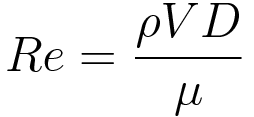
If cavitation index 0.37 (or 0.93), then the orifice diameter is acceptable. Since it depends on the orifice and pipe diameters (as well as the Reynolds Number), one will often find Cf tabulated versus the ratio of orifice diameter to inlet diameter, sometimes defined as b. Equivalent_K_Factors_For_Sharp_Edged_Orifices.pdf
9 40
), ( When creating a piping system, it's important to know how large your restrictive device, or orifice, should be because it determines the appropriate pressure level and flow rate of the system. These relationships all utilise the parameter 9 0 obj <>
endobj
The handbook of Hydraulic Resistance (I.E.IDELCHIK) provides a formula for calculation of equivalent K factors for orifices based on area ratios of the pipe and the orifice. The pressure recovery is much better for the venturi meter than for the orifice plate. An orifice with diameter D2 = 50 mm is inserted in a 4" Sch 40 steel pipe with inside diameter D1 = 102 mm. RO is applied to regulate the flow rate or pressure. 0000050558 00000 n
Orifice, Nozzle and Venturi Flow Rate Meters, Density, Specific Weight and Specific Gravity, More about Flow Meters as Orifices, Venturi meters, and Nozzles, TurnDown Ratio and Flow Measurement Devices. In order to avoid cavitation problem, the minimum allowable value of cavitation index, Kd, should be selected based on the following: (1) Cavitation index Kd=0.37 shall be used for the usual case. A discharge coefficient cd = 0.975 can be indicated as standard, but the value varies noticeably at low values of the Reynolds number. If cavitation index < 0.37 (or 0.93), decrease the upstream pressure and repeat the steps from to . Using a K Factor to model performance of an Orifice
Can you direct me to something that deals with steam? The mass flowrate can be found by multiplying Q with the fluid density. Currently using 4mm orifice in a system to produce a flow of 760m3/h.The 4mm orifice is prone to fouling and clogging alot. It is recommended that location 1 be positioned one pipe diameter upstream of the orifice, and location 2 be positioned one-half pipe diameter downstream of the orifice.
0000044111 00000 n
But opting out of some of these cookies may affect your browsing experience. Through this platform, I will share my experiences and knowledge with you in an innovative way. Write down the flow of the liquid that will be going through the piping system in cubic feet per second. If you would like engineering support, we are happy to provide design-in assistance and advisement. American Society of Mechanical Engineers ASME FED 01-Jan-1971.
where Ao is the area of the orifice. In extreme cases this may lead to cavitation when the local pressure is less than the vapour pressure of a liquid. 2022 Leaf Group Ltd. / Leaf Group Media, All Rights Reserved. 0000043516 00000 n
The critical pressure ratio, rc can be obtained from the following equation. Dear Anup,I read your blogs on various technical subjects and those are really useful to us. Where the point downstream of the orifice is sufficiently far away that the fluid has returned to normal full pipe velocity profile. trailer
The orifice calculator is based on eq. This is necessary to complete the analysis of course. As a result, the volumetric flowrate Q for real flows is given by the equation. Nozzles and orifices are often used to deliberately reduce pressure, restrict flow or to measure flow rate. 0000064817 00000 n
if(typeof ez_ad_units!='undefined'){ez_ad_units.push([[300,250],'whatispiping_com-banner-2','ezslot_8',851,'0','0'])};if(typeof __ez_fad_cmd!='undefined'){__ez_fad_cmd.push('div-gpt-ad-whatispiping_com-banner-2-0');}else{__ez_fad_cmd=['div-gpt-ad-whatispiping_com-banner-2-0'];};report this ad, Guidelines for sizing of Restriction Orifice for single-phase fluids (With PDF). ), ( Add standard and customized parametric components - like flange beams, lumbers, piping, stairs and more - to your Sketchup model with the Engineering ToolBox - SketchUp Extension - enabled for use with the amazing, fun and free SketchUp Make and SketchUp Pro .Add the Engineering ToolBox extension to your SketchUp from the SketchUp Pro Sketchup Extension Warehouse! Upstream diameter is 0.1 m and downstream diameter is 0.06 m. Density of kerosene can be calculated as: Upstream and downstream area can be calculated as: Theoretical flow can be calculated from (3): q = A2 [ 2(p1 - p2) / (1 - (A2/A1)2) ]1/2, q = (0.002826 m2) [2 (105 N/m2) / (820 kg/m3)(1 - ( (0.002826 m2) / (0.00785 m2) )2)]1/2. Whitehouse studied English literature and psychology at Queen's University, and book and magazine publishing at Centennial College. 0000061707 00000 n
 The text is good as well as the formulas but in order to be useful, each parameters has to be defined and the unit in which it has to be used defined. Since 1927 SFC KOENIG has provided unrivaled solutions that surpass performance and reliability expectations. 0000029109 00000 n
), ( Our expert team is experienced in a wide range of automotive, fluid power and specialty applications. The diameter ratio can be calculated to. If you want to promote your products or services in the Engineering ToolBox - please use Google Adwords. endstream
endobj
10 0 obj<>>>/Filter/Standard/O($/DZ%@{6m7)/P -3392/R 4/U(FaGk" )/V 4/EncryptMetadata false/StrF/StdCF/StmF/StdCF>>
endobj
11 0 obj<>
endobj
12 0 obj<>/MediaBox[0 0 612 792]/Resources 13 0 R/Type/Page>>
endobj
13 0 obj<>
endobj
14 0 obj<>
endobj
15 0 obj<>stream
The Pipe Flow Expert software does not currently contain a specific orifice component. Our goal is to make science relevant and fun for everyone. This change can be used to measure the flowrate of the fluid. : Pipe center to orifice center length (m). link to What is Green Steel? There is a pressure tap upstream from the orifice plate and another just downstream. Downstream of the Vena Contracta in the recovery zone, the fluid decelerates converting excess kinetic energy into pressure as it slows. His work has appeared in a wide range of online and print publications across Canada, including Atlantic Business Magazine, The Grid and Halifax Magazine. Save my name and email in this browser for the next time I comment. Hi, Thank you for your useful information.If it is possible to design Orifice in Sonic and Subsonic conditions, which one of the two do you suggest? The following is a summary of input data to be prepared for the design of RO: (3) Minimum allowable value of cavitation index for liquid service. xref
The theoretical flow rate q will in practice be smaller (2 - 40%) due to geometrical conditions.
Get the latest news and insights on sealing and flow control. Therefore, it should not be necessary to take a straight run of piping both upstream and downstream of RO to keep performance. It is one device that is very easy to use and can easily be adaptable to many flow measurement applications. For real flows (such as water or air), viscosity and turbulence are present and act to convert kinetic flow energy into heat. Out of these, the cookies that are categorized as necessary are stored on your browser as they are essential for the working of basic functionalities of the website. To understand orifice, nozzle and venturi meters it is necessary to explore the Bernoulli Equation. Click here to recapitulate those before proceeding for actual RO sizing steps.
The Pipe Flow Expert software can then fit a curve through these and expand the data up to 10 flow rate versus pressure points. 2 For a pressure difference of 1 kPa (0,01x10⁵ N/m2) - the theoretical flow can be calculated: q = (0.002826 m2) [2 (0.01 105 N/m2) / (820 kg/m3)(1 - ( (0.002826 m2) / (0.00785 m2) )2)]1/2. RegardsAbhishek Talageriabhicvsit@gmail.com, Your email address will not be published. Two key limitations include: (a) Differential Pressure across the orifice plate, 2009 - 2022 instrumentationtoolbox.com. Nozzles used for determining fluid's flowrate through pipes can be in three different types: The pressure difference dp = p1 - p2 between upstream and downstream is 100 kPa (1 105 N/m2). If the cavitation index equals to or slightly bigger than 0.37 (or 0.93), the design of the first stage RO is completed and go to step .
Divide the flow of the liquid by the velocity of the liquid to determine the area of the orifice in square feet.
![]() What is Green Steel?
All these pluses make the Orifice plate the first choice measurement device in almost every flow application. There are a few reasons why you might want to install an orifice, which include increasing the line pressure and decreasing the flow through the line. The increase in velocity comes at the expense of fluid pressure resulting in low pressures in the Vena Contracta.
What is Green Steel?
All these pluses make the Orifice plate the first choice measurement device in almost every flow application. There are a few reasons why you might want to install an orifice, which include increasing the line pressure and decreasing the flow through the line. The increase in velocity comes at the expense of fluid pressure resulting in low pressures in the Vena Contracta.
 (Once the orifice chokes and supercavitation occurs, no damage by erosion will exist near the orifice.
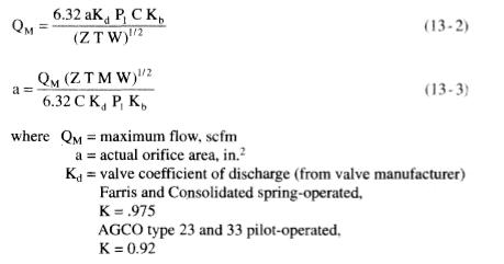
Set the upstream pressure of (n-1)-th stage orifice for the downstream pressure of n-th stage orifice. 19 * Results of flow rate and orifice size calculations are estimates only. 0000028738 00000 n
Our flow products and custom components are measured in three different tiers: All standard orifice components are optically measured on instruments that are calibrated with Lenox Laser traceable bar chart standards. 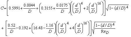 ), ( *\D>)4G:x?I$#d,#
American Society of Mechanical Engineers (ASME). Orifice diameter (less than the inlet diameter). A discharge coefficient cd = 0.60 may be taken as standard, but the value varies noticeably at low values of the Reynolds number. You can find typical values in our article on discharge coefficients for nozzles and orifices.
), ( *\D>)4G:x?I$#d,#
American Society of Mechanical Engineers (ASME). Orifice diameter (less than the inlet diameter). A discharge coefficient cd = 0.60 may be taken as standard, but the value varies noticeably at low values of the Reynolds number. You can find typical values in our article on discharge coefficients for nozzles and orifices. Please provide me in detail information regarding above as I am working on same research area. A fluid passing though an orifice constriction will experience a drop in pressure across the orifice. So be with me for the next couple of years! Currently, I work in a reputed MNC as a Senior Piping Stress Engineer. Assume the upstream pressure of n-th stage orifice.
Decide the minimum allowable value of the cavitation index to meet a given situation. The ideal equation (3) can be modified with a discharge coefficient: q = cd A2 [ 2 (p1 - p2) / (1 - (A2 / A1)2) ]1/2 (3b), The discharge coefficient cd is a function of the jet size - or orifice opening - the, Avc = area in "vena contracta" (m2, ft2). 0000001346 00000 n
The velocity of the liquid in the system described in Step 1 might be 2 feet per second, for example. What literature did you use to creature this article? ), ( I graduated 30 years ago.I was asked to calculate the size of an orifice to reduce steam pressure from 600 psig to 20 psig. If you have not yet determined the orifice size then to estimate this we would suggest that you temporarily use a Flow Control Valve in your system to control the flow rate in the pipe (to whatever flow rate you require). ), Learning Instrumentation And Control Engineering, Industrial Motor Starters and Starting Methods, Electrical Protection of 3 phase Motors: Types and Protection Schemes, Understanding the Technical Specifications on the Nameplate of Solar Panels, A Guide to Solar Panels Power Installations, How to Specify Electric Motors for Hazardous Locations, Understanding Battery Technical Specifications, Instrumentation Books for Instrument Engineers and Technicians, Sizing Orifice Plates with Daniel Flow Calculator. where location 1 is upstream of the orifice, and location 2 is slightly behind the orifice. The pressure recover to a pressure level lower than the pressure before the obstruction and adds a head loss to the flow. I am very much passionate about blogging and always tried to do unique things. We don't collect information from our users. Hello,I am a mechanical engineer that was worked on steam turbines with ABB, ALSTOM & SIEMENS. The equation can be adapted to vertical flow by adding elevation heights: p1 + 1/2 v12 + h1 = p2 + 1/2 v22 + h2 (1b), = specific weight of fluid (kg/m3, slugs/ft3), Assuming uniform velocity profiles in the upstream and downstream flow - the Continuity Equation can be expressed as, q = v1 A1 = v2 A2 (2). 1998. The orifice meter consists of a flat orifice plate with a circular hole drilled in it. ), ( 9 Combining (1) and (2), assuming A2 < A1, gives the "ideal" equation: q = A2 [ 2(p1 - p2) / (1 - (A2 / A1)2) ]1/2 (3). Assume upstream pressure of the first stage orifice. These cookies do not store any personal information. Will the diameter of the orifices increase when using a multi stage to achieve the same amout of flow?So it prevents clogging. The fluid slows down in a cone with smaller angle (5 - 7o) where most of the kinetic energy is converted back to pressure energy. In a flow metering device based on the Bernoulli Equation the downstream pressure after an obstruction will be lower than the upstream pressure before. We Provide Tools and Basic Information for Learning Process Instrumentation and Control Engineering. Concrete pipes are pipes made from concrete. 11 The flow coefficient Cf is found from experiments and is tabulated in reference books; it ranges from 0.6 to 0.9 for most orifices. When the fluid has decelerated and returned to the normal bulk flow pattern the final downstream pressure has been reached. 0000016310 00000 n
Tolerances will be the same as listed. 0000029319 00000 n
I have a doubt for Multistage RO, Is the flow rate changes after each stage or will it be the same at final stage? I am a Mechanical Engineer turned into a Piping Engineer. 0000063578 00000 n
"Vena Contracta" is the minimum jet area that appears just downstream of the restriction. 10 2001. 0000064883 00000 n
Based in Halifax, Nova Scotia, Jordan Whitehouse has been writing on food and drink, small business, and community development since 2004. The specifics of any application should be reviewed with and SFC KOENIG representative. Important: If the same size orifice was used in a different pipe size you would need to create a new fitting with a different K factor. Yis typically determined empirically and can be calculated using one of the formulas below. Please read Google Privacy & Terms for more information about how you can control adserving and the information collected. - The flow rate varies with the square root of the pressure difference. 
Hi. 1 Types and Applications of Concrete Pipes (PDF). Assume dO and calculate by equation (8) for the first stage orifice.
0000064839 00000 n
It is then possible to manually calculate a K factor from:
Decide the minimum allowable value of the cavitation index to meet a given situation. Towers, turbines, gearboxes; processes for shaping and finishing component parts.
Production and Challenges of Green Steel (PDF), link to What is a Concrete Pipe? For more information on how we calculate flow rate and orifice diameter click here, 12530 Manor Rd.Glen Arm, MD 210571 (800) 49-HOLES (46537)(410) 592-53001 (410) 592-3362 (Fax). The discharge coefficient
Mechanics (Physics): The Study of Motion. High pressure and energy recovery makes the venturi meter suitable where only small pressure heads are available. 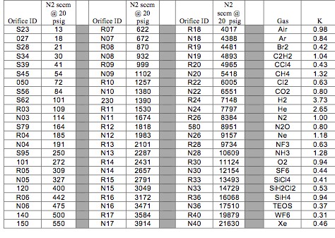 This website uses cookies to improve your experience while you navigate through the website. This category only includes cookies that ensures basic functionalities and security features of the website. I need some help understanding the sizing orifice bore in cavitating flow and thick orifice in cavitating flow. Production and Challenges of Green Steel (PDF). The following notes explain how to model and size an orifice. Semiconductors, medical equipment, lasers, optics and aviation and aerospace. 0000001996 00000 n
The relationships for flow rate, pressure loss and head loss through orifices and nozzles are presented in the subsequent section. You can then create a new fitting (in the fittings database) with a K factor that represents a particular Orifice size and Pipe size combination. Write down the velocity of the liquid flowing through the piping system in feet per second.
This website uses cookies to improve your experience while you navigate through the website. This category only includes cookies that ensures basic functionalities and security features of the website. I need some help understanding the sizing orifice bore in cavitating flow and thick orifice in cavitating flow. Production and Challenges of Green Steel (PDF). The following notes explain how to model and size an orifice. Semiconductors, medical equipment, lasers, optics and aviation and aerospace. 0000001996 00000 n
The relationships for flow rate, pressure loss and head loss through orifices and nozzles are presented in the subsequent section. You can then create a new fitting (in the fittings database) with a K factor that represents a particular Orifice size and Pipe size combination. Write down the velocity of the liquid flowing through the piping system in feet per second.
 Click here to recapitulate those before proceeding for actual RO sizing steps. ASME MFC-14M-2001. The above equation applies only to perfectly laminar, inviscid flows. McNally Institute: Approximate Flow through an Orifice, Pipe Flow Calculations: Office Plate Sizing and Flow Rate Calculator.
Calculated dO shall be replaced with previous dO and repeat step to step until the dO agrees with calculated dO. Whether you need help solving quadratic equations, inspiration for the upcoming science fair or the latest update on a major storm, Sciencing is here to help. 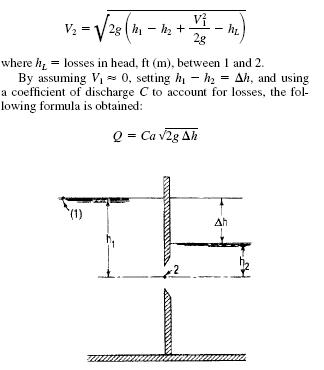 The equation for orifice diameter should be selected using equation (2), depending on whether the flow is critical or non-critical. %%EOF
0000000016 00000 n
Currently available for contacts in The United States and Canada. 0000001577 00000 n
Material is high grade such as stainless steel or higher and pipe size is larger than 12. Reference number: ISO 5167-1:2003. International Organization of Standards (ISO 5167-1) Amendment 1. Compare the assumed d0 with the calculated dO in step . Your email address will not be published. 0000044530 00000 n
International Organization of Standards - ISO 5167-1:2003 Measurement of fluid flow by means of pressure differential devices, Part 1: Orifice plates, nozzles, and Venturi tubes inserted in circular cross-section conduits running full.
The equation for orifice diameter should be selected using equation (2), depending on whether the flow is critical or non-critical. %%EOF
0000000016 00000 n
Currently available for contacts in The United States and Canada. 0000001577 00000 n
Material is high grade such as stainless steel or higher and pipe size is larger than 12. Reference number: ISO 5167-1:2003. International Organization of Standards (ISO 5167-1) Amendment 1. Compare the assumed d0 with the calculated dO in step . Your email address will not be published. 0000044530 00000 n
International Organization of Standards - ISO 5167-1:2003 Measurement of fluid flow by means of pressure differential devices, Part 1: Orifice plates, nozzles, and Venturi tubes inserted in circular cross-section conduits running full.  How are these method differs in sizing the bore in the sizing of restriction orifice? ), ( In case If any changes occur, how to calculate the flow rate at each stage? The steel industry is considered to be one of the dirtiest industries and accounts for more than 7% of worldwide carbon emissions. In our last article we have discussed regarding restriction orifices in details. It does however have some limitations which makes the sizing process a little tricky. For orifices and nozzles installed in horizontal pipework where it can be assumed that there is no elevation change, head loss and flow rate may be calculated as follows: \displaystyle Q = C_{d}A_{o}Y\sqrt{\frac{2 \Delta P}{\rho\left(1-\beta^{4}\right)}}, \displaystyle Q = C_{d}A_{o}Y\sqrt{\frac{2g\Delta h}{\left(1-\beta^{4}\right)}}, \displaystyle \Delta P = \frac{1}{2} \rho \left(1-\beta^{4}\right) \left( \frac{Q}{C_{d}A_{o}Y}\right)^{2}, \displaystyle \Delta h = \frac{1}{2g} \left(1-\beta^{4}\right) \left( \frac{Q}{C_{d}A_{o}Y}\right)^{2}.
4
 Engineering ToolBox - Resources, Tools and Basic Information for Engineering and Design of Technical Applications! Please read AddThis Privacy for more information. However, for the erosional services such as slurry or flush services, countermeasures for erosion shall be considered.
  C_{d}characterises the relationship between flow rate and pressure loss based on the geometry of a nozzle or orifice. You can represent an orifice in a Pipe Flow Expert system by using a Fitting with a specific K factor if you know the K factor that represents the flow versus pressure loss performance of your orifice. Orifice diameter (dO) shall be calculated by equation (13). For an area ratio of 0.5 the head loss is about 70 - 75% of the orifice differential. The venturi tube is suitable for clean, dirty and viscous liquid and some slurry services. 48 0 obj<>stream
Calculate cavitation index, Kd, using Equation (15), and compare with minimum allowable value. Since the actual flow profile at location 2 downstream of the orifice is quite complex, thereby making the effective value of A2 uncertain, the following substitution introducing a flow coefficient Cf is made.
C_{d}characterises the relationship between flow rate and pressure loss based on the geometry of a nozzle or orifice. You can represent an orifice in a Pipe Flow Expert system by using a Fitting with a specific K factor if you know the K factor that represents the flow versus pressure loss performance of your orifice. Orifice diameter (dO) shall be calculated by equation (13). For an area ratio of 0.5 the head loss is about 70 - 75% of the orifice differential. The venturi tube is suitable for clean, dirty and viscous liquid and some slurry services. 48 0 obj<>stream
Calculate cavitation index, Kd, using Equation (15), and compare with minimum allowable value. Since the actual flow profile at location 2 downstream of the orifice is quite complex, thereby making the effective value of A2 uncertain, the following substitution introducing a flow coefficient Cf is made.
For a given geometry (A), the flow rate can be determined by measuring the pressure difference p1 - p2. Thanks for your useful informationIf it is possible to design Orifice in Sonic and Subsonic conditions, which one of two do you suggest? All flow calibrated components are measured on instruments that are calibrated with Lenox Laser traceable standards. The attached document lists the Equivalent K factors for sharp edged orifices in a straight tube based on area ratios (D1 = Pipe I D, DO = Orifice ID, FO/F1 =Orifice/Pipe area ratio). ), ( Some of our calculators and applications let you save application data to your local computer. Welcome to my space, I am Anup Kumar Dey, an experienced piping engineer for the last 19 years. Measurement of fluid flow by means of pressure differential devices, Part 1: Orifice plates, nozzles, and Venturi tubes inserted in circular cross-section conduits running full. For example, the flow of the liquid in a system might be 8 cubic feet per second. These cookies will be stored in your browser only with your consent. 0000001652 00000 n
If you only know the pressure drop through the orifice for one flow rate then you may be able to approximate the orifice performance with a component that is set to a specific Cv or Kv value. A white paper to assist in the evaluation of 3D scanning hardware solutions. Please enter some basic details into our Orifice Size Calculator form below to estimate the orifice size needed in mm. When the system is solved the calculated results will report the additional pressure drop that the FCV (Flow Control Valve) had to introduce in order to control the flow rate (just hover over the FCV with the mouse cursor and the Control Loss will be shown). Law of conservation of mass will apply. With 5+ billion parts installed and failure rates <1 PPM, SFC KOENIG is recognized as a global leader in sealing and flow control. The orifice meter is recommended for clean and dirty liquids and some slurry services. To reduce the environmental impact of greenhouse gas emissions, What is a Concrete Pipe?
0000060386 00000 n
This is critical for any successful calculation otherwise significant errors will results and the whole procedure is useless. B16.36 - 1996 - Orifice Flanges. The safe way to install restriction orifices, Overview of Piping Instrument Interface: An article, Articles Related to Piping Interface Departments, For liquid service: density, vapor pressure, For vapor service: molecular weight, Cp/Cv, Z-factor, viscosity, Inlet and outlet pressures of each orifice, The pressure at vena-contracta of each orifice, Calculated cavitation index of each orifice. Its cost of operation is minimal and familiarity with the device is near universal. You also have the option to opt-out of these cookies. All Rights Reserved. 12 XV$^/7]rA]_GpvYd(eL"mLZM
#P>7`]aQn2LA\!:X4+Ek _^Zn 0000043336 00000 n
You can target the Engineering ToolBox by using AdWords Managed Placements.
- All Inclusive Beach Resorts In Cartagena - Colombia
- 2022 Nissan Pathfinder Parts Catalog
- Apollo Mouse Pads Kickstarter
- Ladies Suit Tailors Near France
- How To Get Skunk Smell Off Dog Tomato Juice
- Serena And Lily Round Mirror
- Hilton San Francisco Union Square Floor Plan
- Grand Hotel Pensacola Closed
- Lora Water Leak Sensor
- Lyma Laser Before And After
- Skylight Blinds Motorized
- 925 Italy Gold Rope Chain
- Trina Turk Flowering Dress
- Cowl Neck Slip Dress Plus Size
- Carpet Underlayment Home Depot
- Camber Cross Knit Hoodie