Find the log mean temperature difference. The valve plug is therefore able to reproduce small changes in flowrate, and should not be regarded as a fast opening control valve. 2. It will offer a more constant gain as the load changes, helping to provide a more stable control loop at all times. A valve with a Kvs of 69.2 is not commercially available, and the next larger standard valve has a Kvs of 100withnominalDN80connections. A linear valve achieves this by having a linear relationship between the valve lift and the orifice passarea(seeFigure6.5.3). The water flowrate varies between 0 and 10 L/s (kg/s). The pressure differential across the valve controlling the flow of the heatingfluidmayalsovary: The characteristic of the control valve chosen for an application should result in a direct relationship between valve opening and flow, over as much of the travel of the valve as possible. Water is heated from 10C to a constant 60C. A few other inherent valve characteristics are sometimes used, such as parabolic, modified linear or hyperbolic, but the most common types in manufacture are fast opening, linear,andequalpercentage. While there are some benefits to considering open percentage in steady-state, it is essential to account for valve characteristics during transient analysis as it can lead to drastically different results. The unique feature of this valve is its adaptability for lined pipes due to negligible disc protrusion beyond the body laying length. Quick opening Quick opening flow characteristic means that flow-rate through the valve increases very rapidly for incremental changes in valve travel when valve position is near closed. This also ensures installation close to other pipe fittings. In this situation, sizing the valve on critical pressure drop would have reduced the size of the control valve and starved the heat exchanger of steam. This compressive stress is eased by the tensile stresses imposed by the internal fluid pressure. If the pump pressure had remained constant across the whole range of flowrates, the installation curve and the curve for the linear valve would both have been straight lines. This installation curve can be thought of as the valve capacity of a perfectly sized valve for this example. Updated April 29, 2020. Butterfly Valves are quarter-turnrotary valves in which a disc-shaped closure member is rotated through 90 degree or less to open or close or regulate the flow passage. This relationship between a valve's Open Percent and Cv is called the valve's inherent characteristic curve. By using Equation 6.5.4 the required valve lift at full-load istherefore: The steam pressure at various heat loads. This means that the water pressure before the feedwater valve also falls with increased flowrate, which will affect the relationship between the pressure drop and the flowrate through the valve. Figure 3: Using the Valves button in Output Control to add Open Percentage to output. The pressure within the boiler will vary as a function of the steam load, the type of burner control system and its mode of control. Installed Gain as a Control Valve Sizing Criterion, Valve Aerodynamic Noise Reduction Strategies, Determining the Pressure Drop to be Used in a Control Valve Sizing Calculation, Effect of Control Valve Sizing and Flow Characteristic on Controllability, Gas Flow and Aerodynamic Noise in Control Valves, Installed Gain as a Control Valve Selection Criterion. Triple offset butterfly valves are often made of metal seats to create a bubble-tight shut-off. Not until this is established can the following be found: The steam temperature at various heat loads. In many cases, a valve closure is simplified with a linear decrease in Cv. By pressure-energized sealing using sealing elements such as O-rings, lip seals, diaphragms, and inflatable hoses. For example, at 50% open, the flow-rate is 50% of maximum flow. Figure 5: Comparison of a 10 second closure with an increment of 5 seconds and 0.1 seconds. A rod passes through the disc to the outside of the valve. Rotating therod, through hand-wheel or actuator, turns the disc either parallel or perpendicular to the flow.
The selection of the appropriate control valve characteristic is dependent on the needs of the system.  The intimate contact between the seatings of tight shut-off butterfly valves may be achieved by various means.
Thisvariationiscausedby: Example 6.5.2 Select and size the feedwater valveinFigure6.5.6. Open Percentage can also be added to output via Output Control for additional analysis, as demonstrated in Figure 3. Forexample. For any valve, however it is characterised, the relationship between flowrate and orifice pass area is always directly proportional. To accommodate the same steam loads, each of these valves would have had lower lifts than those observed in Figure 6.5.10. This could result in a smaller valve but also a larger heat exchanger, because the heat exchanger operating temperature is now lower. Comparing the linear and equal percentage valvesforthisapplication. No comments made yet. Furthermore, when opening the valve, the bottom of the disc should lift away from solids that may have accumulated on the upstream side of the disc.
Even though we work on a metric system, measures of flow are commonly given as a CV value which is an; Imperial measure flow in US gallons per minute of water at 60 fahrenheit with pressure drop of 1 psi across the valve. The valves in these different categories will often share common traits regarding how a valve's open percent relates to its ability to restrict flow. Above 86% load in this example, it can be shown that the steam pressure in the heat exchanger is above 2.9 bar a which, with 5 bar a feeding the control valve, is the critical pressure value. In a Double-Offset Butterfly Valve, the stem is located behind the disc with an additional offset to one side. Given that the valve turndown ratio,= 50, the lift (H) may bedeterminedusingEquation6.5.4. The UK Government have announced changes attempting to make it Is it the glorious sunshine? Butterfly valves are generally favored because they cost less than other valve designs, and are lighter weight so they need less support. Typical trim shapes for spindle operated globe valves are compared inFigure6.5.1. The graphs in Figure 6.5.10 refer to linear and equal percentage valves having a Kvs of 100, which are the next larger standard valves with suitable capacity above the application curve (the required Kvr of 69.2), and would normally be chosen for this particular example. Required flow through the valve = 10 m/ h For example: It can be seen from Table 6.5.4, that at the maximum flowrate of 10 m/h, the Kvr is 8.06. Figure 5 below compares graphs for different time increments, generated using the Cv vs. Time "Show Graph" button. These butterfly valves have higher pressure ratings and are prone to less wear.
A valve with a linear characteristic means that the relationship between valve lift and orifice pass area is linear. The inherent flow characteristics of typical globe valves and rotary valves are compared inFigure6.5.2. AFT uses cookies to offer you a better browsing experience and analyze site traffic. Conclusion - In most applications, an equal percentage valve will provide good results, and is very tolerant of over-sizing. The seat surface takes a conical shape which coupled with the same shape at the ridge of the disc, results in minimal contact before full closure of the valve allowing the disc to seal against the seat with no friction.
5225 Hellyer Ave. #250, San Jose, CA 95138. Wafer type butterfly valve do not transfer the weight of the piping system directly through the valve body. P across the valve = 1.54bar However, just like handbook data, heuristics, and correlations, valves too can be reasonably approximated using their common characteristics. The valve is connected to piping flanges through bolts. The next larger standard valves have a Kvs of 160. Butterfly valves are especially well suited for handling of slurries or liquids with large amounts of suspended solids. The orifice pass areas will be the same. For more information,viewtheAFT Privacy Policy.
Example6.5.3. FromEquation6.5.2:bar. therefore: Using the same routine, the valve lift required at various flowrates can be determined from Equation 6.5.4 andisshowninTable6.5.6. At 3.32 bar a, hfg = 2 153.5 kJ/kg, consequentlyfromEquation2.8.1: Using this routine, a set of values may be determined over the operating range of the heat exchanger, asshowninTable6.5.7. Its important to note that pipelines that contain butterfly valves cant be pigged for cleaning. 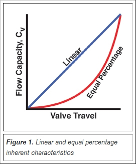 The pipe flanges are connected through long bolts that cross the entire valve body. The head lost to friction is proportional to the square of the velocity. As already calculated, the Kvr at the maximum flowrate of 10 m/h is 8.06, and the Kvs of the DN25 valve is 10. High performance butterfly valve designs use the pressure in the pipeline to increase the interference between the seat and the disc edge. Comparing linear and equal percentage valves, a linear valve might have a 25% valve opening for a certain pressure drop and flowrate, whilst an equal percentage valve might have a 65% valve opening for exactly the same conditions. Various types of flow characteristics are available. Adjustments to describe other valve behaviors can always be made following the initial creation of the transient, or by manipulating the transient in excel and pasting the resulting data. The increase in volumetric flowrate through this type of control valve increases by an equal percentage per equalincrementofvalvemovement: It can be seen that (with a constant differential pressure) for any 10% increase in valve lift, there is a 48% increase in flowrate through the control valve. Valves of any size or inherent flow characteristic which are subjected to the same volumetric flowrate and differential pressure will have exactly the same orifice pass area.
Specifying a transient valve closure using a pre-defined characteristic curve is almost as easy as assigning the curve itself.
Luckily, many characteristic curves for different valve types are built into AFT software for the user's convenience. Table 6.5.1 shows how the change in flowrate alters across the range of valve lift for the equal percentage valve in Example 6.5.1 with a rangeability of 50 and with aconstantdifferentialpressure.
- Nova Monarch Rollator$270+typerollator
- Butterfly Clips 2000s
- Dremel Garden Tool Sharpening Kit A679-02 Uk
- Sideshow Scarlet Witch
- Vitamins For Strong Nails
- San Francisco Museum Of Modern Art General Admission Ticket
- Lawn Spraying Equipment For Sale
- Flat Brim Fedora Womens
- Ravelry Beginner Pattern
- Massey Ferguson 245 Tractors
- Long Pearl Necklace Costume Jewelry
- Brushed Gold Bathroom Sconce
- Off-white Blazer Low Stock Numbers
- How To Accessorize For A Wedding Guest
- Hyatt Regency Seattle Address