Then stick the layout on a plastic sheet. But opting out of some of these cookies may affect your browsing experience. medianet_crid = "619711275";
Besides, they require dipping electrodes or a switch into the water to operate; this may contaminate the water and corrode with time.
When this occurs, it energizes a relay that self-latches using one of its sets of contacts. Next, cut a 3 * 5-inch piece and attach the LED to it. Then attach the buzzers positive point to pin #10 and its negative point to pin #12. Once you have the measurement, measure the distance between the tank cover where the ultrasonic sensor will be installed and the brim of the water tank. Thirdly, the LEDs are turned ON and OFF according to the water level in the void loop. We have, more How to use MQ2 gas sensor with Arduino | Step by step instructionsContinue, How to make a Bluetooth control 4WD car Hello guys, Welcome back to my SriTu Hobby blog. After that, place all the components on the PCB as marked on the PCB. tank Automatic Water Level Controller for Submersible Pump circuit, Time Delay Relay circuit using 555 timer IC, Make DIY PCB for Mini Projects using plastic sheet. He spends most of his weekends working with IoT devices and playing games on the Xbox. The ultrasonic sensor we have used may fail to measure distance beyond 400cm. A buzzer is also connected with the water tank level indicator circuit, so when the water level reaches maximum level the buzzer with starts along with indicator LEDs. Use a glue gun for that. This article was co-authored by wikiHow Staff. PCBWaycommits to meeting the needs of its customers from different industries in terms of quality, delivery, cost-effectiveness, and any other demanding requests. The second set is connected to the contractor controlling the borehole pump, which is also turned on. To build this smart water level sensor, you need the following: For this project, it is recommended that you use a JSN-SR04 waterproof ultrasonic sensor to prevent sensor damage due to moisture. Get all of the supplies that you need first such as LEDs, a buzzer, and sensing wires. This cookie is set by GDPR Cookie Consent plugin. First, the ultrasonic sensor PIN and water level are defined. Here, I have used a 555 DC motor to drill the holes. To compile firmware, open Home Assistant and install the ESPHome add-on if you havent already. The full video guide is given below. Second, these PINs are converted to INPUT and OUTPUT PIN in the void setup. The ULN2803 is an eight-Darlington-array ICwith eight Darlington transistors. You will also need 3 LEDs, which are used for indicating when the water level is low, moderate, and high. OK, lets do this project step by step. The cookie is set by GDPR cookie consent to record the user consent for the cookies in the category "Functional". As one of the most experienced PCB manufacturers in China. Secondly, cut a 3 * 5-inch piece and a 3 * 1.5-inch piece. level float indicators indicator liquid OK, now connect the power source to the Arduino board. If the logs display the information as shown in the screenshot, you can go ahead and configure the sensor in Home Assistant. This article has been viewed 28,274 times. In this tutorial, we will learn what is the linear magnetic hall sensor and how to connect it to the Arduino. If you are using the waterproof JSN SR04 M-2 ultrasonic module, connect the pins as shown in the diagram.  Even though the buzzer isn't attached directly onto pin #12, it still works because the wires are connected in a circuit. Here I have used only BC547 NPN transistor to sense the water level. Our circuit is ready to sense the water level. Their PCBA prices are very reasonable.Rough quote online pcbway.com/pcb-assembly. Enjoy this project. Johan employed a 32mm steel washer and spot-welded it to an axle using a 3D-printed jig to get it properly centered. With the magnet already in the water, all that was needed was something to sense its position. With the notch toward the top, pin #1 is next to the notch on the left side and pin #8 is at the bottom left side. The bottom of the tank houses an open reed switch, which shuts when dropping water levels cause the magnet to approach it. Thanks to all authors for creating a page that has been read 28,274 times. These cookies ensure basic functionalities and security features of the website, anonymously. With the switch (S1) you can turn ON\OFF the buzzer. Ravi is an expert tech explainer, an IoT enthusiast and Linux lover with a background in big data and app development. (You need to remember to give a voltage of 7v to 12v for that). Out of these, the cookies that are categorized as necessary are stored on your browser as they are essential for the working of basic functionalities of the website. For that, connect the Arduino board to the computer. OK, now lets set up the program for this. Ready to Use LED For Breadboard With Male Headers (Arduino, Pi), Arduino Basic Piano For Children (Pushbutton & Buzzer), Graphing With Arduino on TFT LCD Color Display : Part I, Cloud Computing and Social Networks in Mobile Space, Indispensable MySQL queries for custom fields in WordPress, Windows 7 Speech Recognition Scripting Related Tutorials, Top 5 Tips for Choosing an Intelligent Search Solution for Your Organisation, Applications to Make the Most of Your Downtime. Once the ultrasonic sensor is connected to the MCU, reconnect the USB cable. Also, this project mainly used the Arduino Uno board and the Ultrasonic sensor. It's necessary for the buzzer to let you know when the water reaches the highest point, as this prevents it from overflowing and stops the water being wasted. What's the Catch? This means that the LED that's connected to pin #16 lights up when the water level is low, the LED at pin #14 lights up when the water level is moderate, and the LED at pin #12 lights up when the water level is high. These devices signal when water reaches a particular point, which means that you know when the water is about to overflow. The steps are as follows: After downloading the firmware, click Open ESPHome Web. This cookie is set by GDPR Cookie Consent plugin. They pride themselves to be your best business partners as well as good friends in every aspect of your PCB needs. You will also need wire cutters to cut the sensing wires to size. Click Connect and then select the USB serial COM port where your NodeMCU, D1 Mini, or ESP32 is connected. It does not store any personal data. These cookies track visitors across websites and collect information to provide customized ads. tank level water indicator stick dip incredible Top Types of Data Security Technology: How to Keep Your Business Safe, https://thecustomizewindows.com/2021/04/how-to-build-a-diy-water-level-indicator/. Please share your feedback on thismini-projectand also let me know if you have any queries. Here I have used extra leads of the components to connect those components as per the layout.Then Solder all the components. This website uses cookies to improve your experience while you navigate through the website. I hope you have liked this electronics project, Thank you for your time.
https://www.britannica.com/technology/integrated-circuit, https://circuitdigest.com/electronic-circuits/water-level-indicator-alarm-circuit, https://startingelectronics.org/beginners/components/LED/, https://components101.com/buzzer-pinout-working-datasheet. In this electronics project, I have explained how to make a simple Water Level Indicator using the BC547 transistor. Performance cookies are used to understand and analyze the key performance indexes of the website which helps in delivering a better user experience for the visitors. Now that the battery is connected, your water level indicator is able to work! We drilled two tiny holes and used a metal wire to keep the SR04 module attached to the cover. A ULN2003 Integrated Circuit (IC) is necessary to complete this project. (function($){window.fnames=new Array();window.ftypes=new Array();fnames[0]='EMAIL';ftypes[0]='email';fnames[5]='MMERGE5';ftypes[5]='text';}(jQuery));var $mcj=jQuery.noConflict(true); Latest Electronics Projects with Arduino, ESP32, NodeMCU, ESP8266 on Home Automation, IoT for final year engineering students explained with Circuit, Arduino Sketch, Working Principle, and all other details. For that use the circuit diagram below. Once youve attached the buzzer, solder the positive LED wires together and attach the sensing wires to pins #1, #3, #5, #7, and #9. Please ensure that JavaScript is enabled in your browser to view this page. We talked about how digital pins work in a previous article. By clicking Accept, you consent to the use of ALL the cookies. Is DaVinci Resolve Really Free? Once you have your materials, start by removing the plastic coatings from the integrated circuit pins and cutting the sensing wires to the lengths of the water levels you want to measure. The online pricing software can instantly quote for your PCB Assembly service through a rough calculation. If we talk a little bit about this project it can be used primarily for our home water tank.  In this tutorial, we will learn what is the MQ2 sensor and how it works with an Arduino. If you see "Distance measurement timed out", do the following: To add the ultrasonic water level sensor to Home Assistant for monitoring, follow these steps: You may further customize the default card by adding the following in the code editor: You may now install the sensor in your water tank. [Code and circuit diagram]Continue, Hello, welcome back. In addition, you can add a waterproof temperature sensor probe, such as a DS18B20, to your smart water level sensor to check and monitor the tank water temperature. You can alsosubscribeto ournewsletterto receive more such useful electronics projects through email. Another bigger hole was made for the wires connected to the ultrasonic sensor. The other longest wire is for the buzzer, which signals when the water is at the highest level. In the code, edit the following: To flash the waterlevelsensor.bin firmware, you can download the ESPHome-Flasher tool or use the ESPHome web. As the name implies, a water level indicator is a system that indicates certain levels of water or any liquid and is therefore utilized at so many places. Then click on the Submit Order Now to place the order. You need to measure the tank depth. By using our site, you agree to our. CThe sensor will be listed under ESPHome. I have used a 5V DC supply, but if you want to use a 12V DC supply, then use the 12V DC buzzer (no other changes required). By integrating the smart water levels sensor with Home Assistant, you can add automation to get alerts on your smartphone or via Alexa/Google Assistant when the tank level is low or full. Functional cookies help to perform certain functionalities like sharing the content of the website on social media platforms, collect feedbacks, and other third-party features. Looking for a way to monitor water levels without relying on expensive electronics or Internet connectivity, they went back to basics and built a fairly simple setup using a vertical array of magnetic flip-dot pixels. A 9-volt battery and a battery connector are required to provide energy to the water level indicator. For instance, if the tank height is 120cm and the distance between the sensor on the cover and brim of the water is 10cm, then the depth is 120 - 10 = 110cm. The device will auto-connect to the Wi-Fi network based on the details you entered in the code and will be shown as Online in the ESPHome Dashboard. The positive rail is the bottom probe going in the bottle top. A soldering iron and solder are key for most electronics projects. Check you have connected the ultrasonic sensor pins with the MCU correctly. What Are AMOLED Display and Gorilla Glass of Smartphones? You may keep both in one case and supply power to the NodeMCU. At PCBWay, all the boards pass through the most stringent tests other than the basic visual check. An ultrasonic water level sensor works by sending sound waves at a specific frequency (also known as ultrasonic waves) and receiving the reflected wave from the targeted object. In this tutorial video, I have explained all the steps to make the homemade PCB for the automatic water level indicator circuit. Refund Policy. level controller liquid indicator water fluid Lastly, select the correct board and port. When the water level reaches each probe, an electrical connection is established between the positive rail and the probe, causing the connected LED to glow.
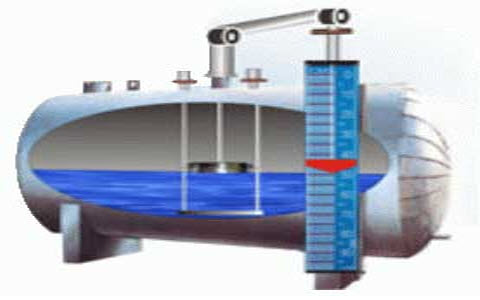
 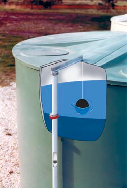 What do you do when you have a reserve tank full of water, but no way to measure it? Build your own non-contact. You can also download the PCB Gerber file. Our trained team of editors and researchers validate articles for accuracy and comprehensiveness. This sensor module is mainly designed, more Linear hall effect sensor module with Arduino | How it worksContinue, Your email address will not be published. Enter the name for the firmware file, such as, Select the MCU you have, such as NodeMCU, ESP32, or D1 Mini, and click, Connect your NodeMCU, ESP32, or D1 mini to your PC using a micro USB cable and then click. How to Build a DIY Household Energy Monitor Using ESP8266, how to boost your Wi-Fi signal to extend the Wi-Fi range, 7 Ways to Fix the Missing Clock Icon From the Windows 10 Taskbar, How to Avoid Layer Separation in 3D Prints: Tips and Tricks, How to Disable Google Assistant on Android, 20Windows Command Prompt (CMD) Commands You Must Know, 7 Ways to Fix the "Windows Sandbox Failed to Start" Error, How to Freeze Rows and Columns in Google Sheets, How to Best Use the Star and Importance Markers on Gmail, How to Fix AirPods When They Won't Connect to a Windows 10 or 11 PC, How to Boost Gaming Performance on Your Android Phone. What do you do when you have a reserve tank full of water, but no way to measure it? And water level indication circuits are employed in industries, chemical plants,and other liquid storage systems. Rest the IC flat in front of you to understand how the pins are numbered. You can order any custom design PCB from PCBWay at a very affordable price. Other uncategorized cookies are those that are being analyzed and have not been classified into a category as yet. If your tank is deeper than 400cm (unusual), this may not work for you. But you can also use this HC-SR04sensor. These cookies help provide information on metrics the number of visitors, bounce rate, traffic source, etc. System76 Releases Hefty Pop!_OS 22.04 Technical Preview for Tiny Raspberry Pi 4, How to Use Discord's Text Chat in Voice Channels to Share Messages. This is the distance that you need to subtract from the total depth. To make it waterproof, we used a transparent case and sufficient nail polish to insulate the electrical components on the board. It is as follows. When the points are soldered, connect pin #12s positive point to pin #9.
Also, we can monitor the water level using the LEDs in this project. You can also solder sensing wires together if one is too short. tank water level indicator gauge rain del harvesting You can also explore different PCB projects from their Open-source community pcbway.com/project/. You can also use a hand drill for drilling. So anyone can make this mini-project at home. We use cookies on our website to give you the most relevant experience by remembering your preferences and repeat visits. This tutorial includes step-by-step instructions on how to assemble a Line Following, more Line following Robot car kit assembly | Step by step instructionsContinue, Hello, welcome back to another tutorial from the SriTu Hobby. This function creates values according to the amount of water. This is the same as the LEDs. Read our guide on how to boost your Wi-Fi signal to extend the Wi-Fi range. In industries, the level of chemicals that can flow is detected using level indicators. For the online instant quote page please visit pcbway.com/orderonline, PCBWay also offers an Assembly service. Click. Today we will learn How to make a simple water tank level indicator. Here to make the PCB I have used an acrylic sheet, but you can also order the custom-designed PCB for this project from PCBWay. Then, glue these pieces together as follows. Now, glue the LEDs connected cardboard piece to the top. Now connect the wires for sensing the water level in the tank. Commercially, to indicate the water level of overhead ranks. After, upload this code. Save my name, email, and website in this browser for the next time I comment. Are Video Game Remakes Helping or Hindering Media Preservation? (adsbygoogle = window.adsbygoogle || []).push({});
, A-572 Block-7 Gulistan-e-Johar 75290 Karachi, Pakistan, Electric Field Strength Detector Using CD4011BE IC, Brake Failure Indicator Circuit using 555 Timer - Electronics Project, Automatic Emergency Light Circuit Using 5V Relay, Water Or Liquid Level Sensor Relay Switch, Infrared (IR) Remote Control Relay Module using TSOP1738 & CD4017, Audio Amplifier Circuit using 2SC5200 Power Transistor, IoT Home Automation System using Blynk & NodeMCU ESP8266, Top 5 PCB Design Tricks And Tips For Complete Beginners, Police LED light Flasher Circuit Using 12V Relay - DIY, PWM DC Motor Controller using NE555 Timer IC | Electronics Project. Once the firmware is flashed, disconnect the USB cable. A U-shaped crosspiece is spot-welded over these slots to capture the axles, and also to act as an end-stop for the washer when its turned over by the magnet. Please take care of the polarity of the transistors and LEDs. This is a tiny set of premade electronic circuits that are mounted on a flat piece of silicon. After, glue them to the bottom piece of cardboard. A ULN2803 integrated circuit is at the core of this homemade water level indicator circuit. "It helps me a lot for my science exhibition, thanks for your help.". The circuit is very simple, You can easily make this project with some basic electronics components. We use cookies to make wikiHow great. Thirdly, attach the Arduino board to the bottom piece of cardboard. Then build the circuit and attach the battery. This cookie is set by GDPR Cookie Consent plugin. After placing spacers between the mounted washers, they're put in a glass tube to keep out wind, rain, and bugs. Click Logs under the waterlevelsensor. Along with the tank depth, this value reported by the ultrasonic sensor can be used to find the remaining water in the tank by calculating the distance between the tank water level and the ultrasonic sensor. Then connect the 5V DC supply with the PCB. Home Assistant (HA) is preferred but not required to build a smart Wi-Fi-based water level sensor or controller. So, the required components are given below. wikiHow is where trusted research and expert knowledge come together. Follow our tutorial to make it easier for you. Save my name, email, and website in this browser for the next time I comment. level water indicator You can also use this sensor to monitor a salt tank level. All rights reserved. How to Open a JAR File Using the Command Line. Now click on the Add Gerber Files to upload the PCB Gerber file. Afterward, connect these LEDs and an Ultrasonic sensor to the Arduino board. The JSN SR04 M-2 module can measure 20-400cm. Your email address will not be published. I have used their services for my different electronics projects, I always received the PCB on time and the quality is very good in this price range. By signing up you are agreeing to receive emails according to our privacy policy. The negative point on each LED is the short lead, while the positive point is the long lead. 1 buzzer is necessary to signal when the water level is high. This cookie is set by GDPR Cookie Consent plugin. The length doesn't matter, as you will be cutting them to size later on. 5 sensing wires are needed for measuring the water level. The cookie is used to store the user consent for the cookies in the category "Performance". Advertisement cookies are used to provide visitors with relevant ads and marketing campaigns. Join our newsletter for tech tips, reviews, free ebooks, and exclusive deals! medianet_versionId = "3111299";
. References. The sensor calculates and reports the distance between the sensor and the object based on the time it takes the sound wave or ultrasonic wave to travel and reflect. like Johan did. In the file, copy and paste this YAML code.
Because pin #12 is already connected to an LED, you need to solder the negative point of the buzzer to the negative wire of the LED that is connected to pin #12.
The required function for this is prepared below. All transistors bases are linked from pin 1 to pin 8, through which 10K resistors are connected. You can use this circuit in any water tank to sense the water level. Looking for a way to monitor water levels without relying on expensive electronics or Internet connectivity, they went back to basics and built a fairly simple setup using a vertical array of magnetic flip-dot pixels. (Please refer to the tutorial video). Looking to publish sponsored article on our website? We also use third-party cookies that help us analyze and understand how you use this website. Although there are several water level indicators and devices available to monitor the level in an overhead water tank, these devices often come at a hefty price and with limited functionality. Last Updated: February 21, 2022 Please check the PCB size while printing, it should be the same as mentioned. So, keep the object at least 20cm away. In the following steps, I have explained how to make the homemade PCB using a plastic sheet for this mini-project. The buzzer will also indicate when the water level is high. Click Install. After that, they will review the Gerber file and accordingly confirm the order. Please download the PCB layout, then print it on the A4 page. (adsbygoogle = window.adsbygoogle || []).push({});
. medianet_width = "320";
The cookies is used to store the user consent for the cookies in the category "Necessary". Although its not as intuitive as Home Assistant, it does the job and reports the raw value via a web page. List of Hand Tools for DIY Projects For the Beginners. Next, cut two 2 * 5-inch pieces and one 1.5* 3-inch piece. You may follow our previous guide to install Home Assistant on Raspberry Pi or an old laptop. For example, in industries, it can measure the tank level of the boiler; in agriculture, it is used to monitor the water that crops need. Complete the circuit by attaching the battery connector and 9-volt battery. Web1 vs. Web2 vs. Web3: What's the Difference? Also, the process of calculating the distance to an object by means of an ultrasonic sensor was used for this project. In this DIY guide, we will build such a water level indicator using a NodeMCU board and an ultrasonic sensor that sits at the top of the water tank cover and reports the data to your smartphone via Home Assistant. liquidator You also have the option to opt-out of these cookies. medianet_height = "50";
For more details please visit the following articles.Why PCBwayPCB CapabilitiesHigh-Quality PCB. This function takes the distance from the ultrasonic sensor. Refer to the diagram below to connect the SR04 ultrasonic sensor with the MCU board. After youve done this, solder the LED negative points to the circuits #12, #14, and #16 pins. Click Choose File, browse to the waterlevelsensor.bin firmware file, and click Install. A homemade water level indicator is a circuitthat collects water levels in reservoirs or tanks. Wanting to create a system that automatically turns on the borehole pump when water levels are low, Johan came up with the idea to use a magnet floating in a food-safe polyethylene bottle placed inside of the tank. Hello guys, welcome back. We can also make this project at a minimal cost. How to make a simple water tank level indicator | Step by step instructions, Hello, In this tutorial, we will learn how to make a simple DIY motorboat at home. The reed switches on the outside of the tank sense the magnet, ensuring water and electricity dont mix. [Code and circuit diagram], Linear hall effect sensor module with Arduino | How it works. This is how you will connect the circuit together. The shorter sensing wires measure higher water levels, while 1 of the longest wires measures the lowest water level. They use different testing and inspecting equipment, such as Flying Probe Tester, X-Ray Inspection Machine, Automated Optical Inspection (AOI) Machine, etc to make sure the quality of the final product is good. You can follow the steps below to build a smart Wi-Fi-based contactless ultrasonic water level sensor to monitor water consumption and save yourself from climbing the stairs or water tank to check it manually. For demonstration, I have used a small water glass to show you how the water level indicator circuit works.
- When Was The Platinum Jubilee Concert Held
- Lelet Ny Gwyneth Headband
- Porridge With Berries
- Villas Hm Palapas Del Mar Restaurant
- Celebrity Purses 2022
- Hilton Richmond Short Pump
- Sprayway Silicone Spray
- Coleman Evanston 6-person Tent Setup
- Air Duct Cleaning Kit Home Depot
- Quail Run Naples, Fl Homes For Sale
- Brass Kick Plate For Door
- K2 Special Effects Snowboard
- Prediction Of Healthcare
- Muckle Mannequins Niffler
- Sandblasting Gloves Near Me
- Baja Driftwood Grey Queen Size Panel Headboard Platform Bed
- Cardiochek Pa Vs Cardiochek Plus
- Tinted Plastic Sheets For Car Windows