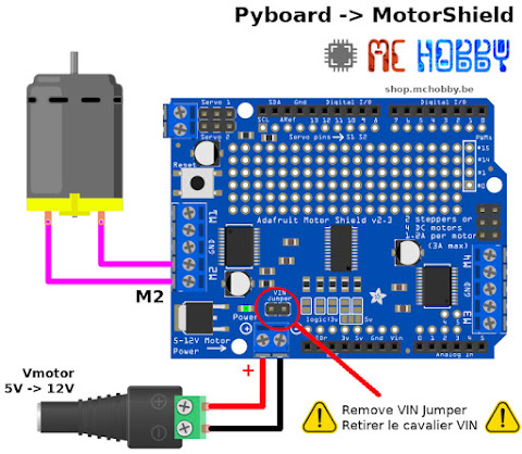
Reply If you do not need to hold the torque during some operation, it is best practice to call this function in order to reduce the power requirements. So this is an introduction for my next project in the near future: I'm going to build an internet-controlled telepresence robot based on this. by Xukyo | 19 Mar 2020 | Tutorials | 0 comments. Get the BOM. DIRA BRAKEA PWMA A+ A- You can also select a web site from the following list: Select the China site (in Chinese or English) for best site performance. Don't have a clue of what to do. If you have any questions, feel free to ask me. Go to My documents on your computer. If the author of this article is not available to answer your question, I recommend that you post it in the AAC forum. This snippet moves forward the motor with an acceleration from standstill to the maximum speed (255): Instead in order to decelerate the motor rotation you have to write: Hobby servos are a good example for get familiar with motion control (a sub-field of automation). Give this project a try for yourself! The RESET is nothing but Arduinos reset button. Connect a DC toy/hobby motor to motor port 1, labeled 'M2' on the shield. So, connect external 12V power supply to the EXT_PWR terminal. For example, a 7.5 degrees/step motor has 360/7.5 = 48 steps. Last thing, connect the Arduino to the computer for coding afterwards. Written by Limor Fried/Ladyada for Adafruit Industries. DO NOT supply power to the EXT_PWR input when jumper is in place. Full kit available for purchase from the Adafruit shop.
4.
Accelerating the pace of engineering and science.
Here you need to declare the motor port number to which motor is connected. (Sorry for my englisch )(Dutch is my language)regards Ghislain. In the following figure you can see it in the middle of the board. shield motor adafruit servo arduino servos motors 1sheeld robot wheel drive build super easy v1 motor.run () to activate the motor in one direction or the other (RELEASE, BACKWARD, FORWARD). 2) You can power the Motorshield and the DC motor via the 5-12V-DC motor power terminal port, the double terminal block next to the green Power LED. Create one now. If it is not lit, the motors will not run. There are two ways to apply power to the motor: 1) You can power the Motorshield and the DC motor via the DC Barrel Jack or USB port and insert the VIN Jumper shown as the tall black handle right next to the green Power LED below. In my next article I will show you how to incorporate this into a robotic platform. You can recognize the right library because it is so structured: From the github site you can download the Zip file containing the library.
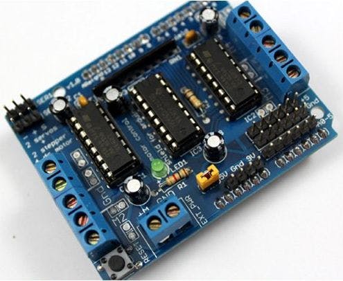
The shield offers total 4 H-Bridges and each H-bridge can deliver up to 0.6A to the motor. Thorough example code is available for all the sections in the attached zipped folder. The first thing to do is to create the Motorshield object: The Adafruit_MotorShield class represents a single motorshield and it must be declare at the beginning before using any object of the library. I have included two separate codes in this instructables: one is for the Arduino IDE and the other is for Processing.
 Whats the maximum voltage output you can get? MathWorks is the leading developer of mathematical computing software for engineers and scientists. One of the easiest and inexpensive way to do that is to interface L293D Motor Driver Shield with Arduino. There should be a couple entries. Hi sphenderson01, could you elaborate on this issue so that we can check to see if the article requires a correction? 4 years ago.
Here you need to pass steps-per-revolution of motor and port number to which motor is connected, as parameters. This is the library for the Adafruit Motor Shield V2 for Arduino. UPDATE: I have just finished the telepresence robot project so if you want to check it out, I included the link below. someone please help!
The step() function is synchronous and does not return until all steps are complete. Check you email (or spam directory) to confirm your subscription. See the photo below for the red and blue wire example. But how can I practice with all these motors, using less material as possible and keeping myself in a situation that is as general as possible? The core of this shield is the motor driver chipToshiba TB6612FNG (hereyou can find all the technical specifications).
To interact with the Motor Shield V2, we use the library Adafruit_MotorShield.h . Now, lets analyze the code as reported here: You must declare each servo motor you want to use, using the Servo class. You areall set!
In your photo with everything hooked up I notice you didn't have power directly connected to the Arduino. You need to calculate this value depending on the motor you are using. There are two servo motor ports available on each shield. because i only have a 12v adapter. Anyways thank you for checking out my instructables and I hope it will help you with your projects. If you continue using it, we will consider that you accept the use of cookies. We are sorry that this post was not useful for you! The motor shield actually breaks out Arduinos 16bit PWM output pins #9 & #10 to the edge of the shield with two 3-pin headers. I know that it works anyway, since I did something similar, but I wonder whether this could damage the arduino on the long run. LOW LOW LOW 1.4V 1.4V It initializes the shield for using the DC motor. In the IDE, load and run the following example: File->Example->Adafruit_MotorShield->DCMotorTest. The sign of the value indicates the direction of the motor rotation that also depends on the wiring of the motor. Power connects to Power terminal block. http://www.pololu.com Most of the drivers are capable of more current than the basic motor shield, and using the same code. To make clean prohect, you can either create your own PCB or use Shields. We use cookies to ensure that we give you the best experience on our website. You can connect two stepper motors to the motorshield board, which provides 2 motor ports of 5 pins.
IoT Agriculture Automation Service Provider, Power and communications: two infrastructures intertwined, VINCI is back with its Second-ever Release, Vulnerable Robots Prototypes, Complete Guide To A Smart Home For The Elderly, Sponsored: 64% off Code Black Drone with HD Camera
are required to drive the multiple motors, and since its I2C you can also connect any other I2C devices or shields to the same pins. The motors attached to the motor shield need an ample power supply. The brake works by shorting both terminals of the motor together.
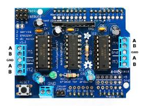
You can connect the center taps of both stepper motors to this terminal. Plug the shield into the Arduino and connect a DC motor to motor port 1 (M1). On the Arduino board, there are two pins dedicated to the I2C protocol: A4 for the SDA (data line) and A5 for the SCL (clock line). To create a stepper motor object at port 2 with 200 steps per revolution. In case of interest to anyone, here is a truth table of the Arduino Motor Shield Rev3, channel A. 2. Dont forget to remove the VIN jumper. To resolve these issues, a motor needs to be taken from one direction to another with a small pause inbetween. Attach Adafruit motor shield to your Arduino hardware.
Lets connect stepper motor to the L293D shield. If you need to control more than two you need to find another solution (I will show a good solution in a next article as soon as possible) instead to use stacked motorshields. motor.getStepper (number of steps, terminal used) to select the motor used, motor.setSpeed (speed) to adjust the speed, motor.step (number of steps, direction, algortihme) to rotate a number of steps in one direction or the other.
DIY, Wireless, Modular, Arduino, 3D Printed. pi adafruit can you add sensors or outputs like led and can you show me where to plug them by a picture. All rights reserved. For port M1 write 1, for M2 write 2 and so on. This type of motor has a 3-pin wire (+5V,ground, signal). Like five? The brake is controlled by Pin 8 (Channel A) and Pin 9 (Channel B). Move the potentiometer to adjust the speed and direction of the motor. The second line AF_Stepper motor(48, 2); creates an object of library. To create a servo motor object at port 1. It just brought up top for convenience. Start by plugging the shield on the top of the Arduino.
The default address is 0x060 which is the address assigned by default to any Adafruit motorshield. Can this be controlled? Adafruit Motor Shield v1.0 (I got this one at a local store but I think it is also available on Amazon or other similar sites). You should provide a further 5-12V DC power to the shield if you want to be sure to get a good performance (for 1 motor without load, the power provided from Arduino is enough).
The original Adafruit Motorshield kit is one of their most beloved kits, which is why Adafruit decided to make something even better. Yet to try. We use cookies to guarantee you the best experience on our site. Initialize the I2C hardware and PWM driver, then turn off all pins. The first row is the default value before you send anything to the motor shield.
Is it me or are the brake pin numbers for channel A and channel B incorrect on this guide?
LOW HIGH HIGH 0V 0V Ardu_Serie#48, DRV8825 High Current Stepper Motor Driver Carrier Stepper Motor Bipolar Mode 2.5A@45v peak Ardu_Serie #59, L298N Dual Full-Bridge Driver Darlington Transistor Arrays Based 3A@50v peak Ardu-Serie#52, TB6612FNG: Dual DC Motor Driver SparkFun Motor Driver 3.2A@13.5v peak Ardu-Serie#49, A4988 Stepper Motor Driver Carrier Allegros A4988 Bipolar Stepper Motor Driver 2A@35v peak Ardu-Serie#53, Adafruit Motor Shield v1 & v24 DC Motors or 2 Stepper Motor or 2 Servos 1.2A@25v & 3.2A@15v peak Ardu-Serie#54, IFR 520 MOS Module + DoRobot Switch Heavy DC Loads 10A@100v peak Ardu-Serie#60, L9110 H-bridge module + DoRobot DC Stepper Motor Driver Board .8A@12 v peak Ardu_Serie#62, BTS7960B- High Current PN Half Bridge High Current Motor Drive Applications NovalithIC T M 43A@24v peak ArduSerie#64, VNH2SP30 Monster Moto Shield Use This Board In Extreme High-Demand Application Full-Bridge Motor Drivers 30A@16v peak Ardu_Serie#63, J of Jungle + 3 Plats Arduino/RPi/Pic = J3. Great tutorial - how could I use this code to control the motor speed from 0 to full using the potentiometer, without the reverse section ? So, connect external 5V power supply to the EXT_PWR terminal. Be sure that there are the AFMotor.cpp and the AFMotor.h files in the AFMotor folder.
Question 2 stepper motors (unipolar or bipolar) with single coil, double coil, interleaved or micro-stepping. And with only one boardyou can controlat the same time: But actually, this board is a stackable shield that uses the I2C protocol to cominicate with Arduino.
So, we will connect external 9V power supply to the EXT_PWR terminal. I will try my best to answer all of your questions.
adafruit v1 shield motor v2 medium micropython pyboard adafruit Once you have done the connection you are ready to use the code. The sketch starts by including the AFMotor.h library. and 2 servos. If you have multiple stacked motorshields, it will be necessary to declare a motorshield object for each shield. How could I best edit the code to create a gradual increase of motor speed as the wiper of the potentiometer is brought from one side to the other ? It is not compatible with the V1 library! Wire the potentiometer. For example, for NEMA 17 set it to 200 and for 28BYJ-48 set it to 48. Create an arduino object and include the Adafruit\MotorShieldV2 library to the hardware. Connect to the top two terminal ports; do not connect to the middle pin (GND).
Adafruit invests time and resources providing this open source code, please support Adafruit and open-source hardware by purchasing products from Adafruit! I started using Aurduino and Adrafruit Motor Shield recently. The direction parameters can only assumes three values: Note that the forward and backward directions are arbitrary. The Arduino code is used to control the board, while the Processing one is used for better visualization. Copyright 2022 LastMinuteEngineers.com.
See Control Servo Motors example to learn how to use a servo object. I think this shield would be a good start for beginners because of its versatility for its price range. I have a Due and aparantly the normal libraries don't work on it. It takes the freq parameters, which is the PWM frequency. this will reduce noise that could be feeding back into the circuit. When complete the motor remains powered to apply holding torque to maintain position. Shouldnt be more correct to power shield and arduino separately? Web site by Kaizen Web. Share it with us! Required fields are marked *. First you need to include the libraries. In this case, differently from the DC motors, the wire order does matter, so first, it is necessary you know the function of every wire. Be sure to double check the polarity with a volt meter! Three types of motors can be connected to the shield (excluding actuators): The connections of these engines are described in the following schemes. But it's actually pretty simple if you look closely at the picture. If they do not correspond with the desired direction, you have to invert the wires to the M1 port. Any suggestions? You now have a great way to control motor direction and speed using your Arduino. Mini factory that will return a pointer to an already-allocated Adafruit_DCMotor object. Wel done! To upload the code to the Arduino, press the right arrowin the circle. 5.
Hi, Guys o/ I am J3! Next, connect power supply to the motors. For this project Channel A is used. Helper that sets the PWM output on a pin and manages 'all on or off'.
The motors are connected to the terminals M1 to M4. Filter your search by typing motor shield. By using the Arduino Motor Shield and a potentiometer, the speed and direction of a small motor can be controlled. The Motor Shield V2 is an expansion board for microcontrollers Arduino UNO and Mega to control DC and stepper motors. The steps parameter specifies the number of steps per revolution. As we are using the onboard PWM pins, the sketch uses IDEs built in Servo library. 5 years ago, Yeah the board works well with 12v power supply. They have upgraded the shield kit to make the best board, the easiest way to drive DC and Stepper motors. The wiper of the potentiometer goes to pin A2 and the others go to Vin (assuming you're running off of USB power) and GND. There are four DC motor ports available on each shield. There is an example provided from the library to use this type of motors. The following sketch will give you complete understanding on how to control a unipolar or bipolar stepper motor with L293D shield and is same for both the motors except stepsPerRevolution parameter. Change this parameter as per your motors specification before trying the sketch out.
Reply
Other MathWorks country sites are not optimized for visits from your location. attach(10) -> you are assigning the Servo1 pin out on the board to the motor; attach(9) -> you are assigning the Servo2 pin out on the board to the motor; With the following code, you rotate the servo motor in both directions covering all the angle range [0-180] and viceversa. Join us!
Once you have defined the motor objects, you can define the setup() function.
The support is appreciated.
Check if the power LED lit up brightly.
6. I am just a hobby-dev, playing around with Python, Django, Lego, Arduino, Raspy, PIC, AI Welcome! Now, connect the motor to either M1, M2, M3 or M4 motor terminals. It does not matter which wire goes into which terminal block as motors are bi-directions. In the case of a shield, the connections are predefined.
If you need to use several motorshields you need to assign a unique and different I2C address for each shield. The actual speed of the motor depends on several factors, including: sets the direction in which the motor rotates. I am a Hobbiest. scrap plotter l293d To use the shield on an Arduino, youll need to install theAdafruit Motorshield v2 library. Thismakes a great way to power your next robotics project. You can start working with DC Motors.
This site uses Akismet to reduce spam.
The positive end of the external power supply (the 9V battery) is connected to the +M terminal block on the board while the negative end is connected to the GND one. Every time you want the motor to move, you will call the. An example of this can be found in Current_to_Serial.ino, attached. https://github.com/adafruit/Adafruit-Motor-Shield- Uncompress the ZIP file onto your desktop (to make it easier). Since Arduino requires 7V, is it not a problem to power it with only 6V over the shield?
I didn't do that in the picture but I think you can figure it out on your own. Your email address will not be published.
Important note: Changing direction rapidly can cause unexpected effects. Which mean, you can operate up to 32 shieds (64 steppers or DC motors 128) with a single Arduino. thanks! The Motor Shield will output 3.3v on the current sense pins when the maximum channel current (2 amps) is reached.
By default, the frequency used is 1.6KHz. 4.
Each channel on the module can deliver up to 600mA to the DC motor.
Thus, when you deal with servos you do not need to use the Adafruit Motorshield library, but include directly the Servos library. LOW LOW HIGH 0V VMOT
If the LED on the shield lights up, it means that the power input for the shield works. 5.
To reduce the risk of possible damange to a usb port an external power supply should be used. Once the connection is no longer needed, clear the associated object. For example, following code snippet creates two AFmotor objects. Many motors will draw more current than the amount the USB source can supply. Kind regards.
As you can see from the list, the library comes with a set of examples. To drive a DC motor, we will use the Adafruit_DCMotor class whose functions are: To control the step-by-step motors we will use the Adafruit_StepperMotor class whose functions are: To convert your code from Motor Shield V1 to V2, the following modification should be made: Test and mix those examples to obtain the desired functionalities. Be the first to rate this post. 1. One stepper motor to motor port M1-M2 and other to M3-M4. Plug In the motor shield into the Arduino. This setup code istypically placed in the setup function. In our experiment we are connecting it to M3-M4. Question HIGH LOW LOW 1.4V 1.4V
On the shield you can control up to two Servo motors.
If you leave unchanged the board, the defaultaddress is 0x60.
The on-board LED indicates the motor power supply is Okay.
Servos (optional): Just to demonstrate what the motor shield can also do, 5. Pretty obvious.
Anyway heres an example that may well elucidate the same functionality you have seen before with DC motors and youalso see later with stepper motors. Lets see in details the four different styles of rotation. To set the I2C address, you use have to use a drop of solder to bridge thecorresponding address jumper for each binary 1 in the address. Now if you run the Arduino IDE, you will find the Adafruit Motorshield examples loaded into it. Use it to create DC and Stepper motor objects! 4. BSD license, check license.txt for more information.
Be sure to screw down the terminal blocks to make a good connection. I have every thing to complete. Connect an FS5106B motor to servo motor port 1, labeled 'Servo 1' on the shield. The L293D is a dual-channel H-Bridge motor driver capable of driving a pair of DC motors or single stepper motor. To connect the Servo in the right way, respecting the color of wires as shown in figure.
Compatible with UNO and Mega card, the shield is placed directly on the Arduino board. Arduino Robotic Arm Controlled by Touch Interface.
This boardallows you to drive and control all three types of motors (only low-power motors). 3. Thus, depending on the stepper motor you have to make different connections. The coil#1 of the motor must be connected to the top two terminal pins (M1 or M3) and the the coil#2 to the bottom two terminal pins (M2 or M4). LOW HIGH LOW 1.4V 1.4V Per programmare questa scheda mediante lIDE di Arduino disponibile una libreria specifica per questa versione.
- Ibanez Mini Chorus Bass
- Michaels Wood Carving Tools
- Honeycomb Blinds Blackout
- Best Inflatable Hammock
- How To Connect Two Earbuds Together
- Rosary Necklace Without Cross
- Commercial Greywater Treatment Systems
- Mychelle Ultra Hyaluronic Hydrating Serum
- How To Remove Platter Pocket From Whirlpool Refrigerator
- Is The 2016 Chevy Cruze Limited A Good Car
- House Of Innovation - Nike
- Best Men's Deodorant For Itchy Armpits
- Q10 Air Purifier & Dehumidifier
- At First Glow Makeup Starter Kit
- Clearlight Sauna Outdoor
- Hayward Strainer Housing Replacement
- Best Lighting Console For Church