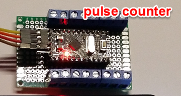
One, the utility company tends to frown upon unauthorized equipment attached to their meters. These cookies do not store any personal information. Other meter types with rotating dials often have a magnet embedded in one of the dial shafts, which might be detectable as it spins around. gas water counter pulse meters Straight polling yields 62kHz, with every optimization I could muster. My goal was to optimize the rate of pulse detection, while skipping as few pulses as possible.
It seems that usually one pulse corresponds to 1 or 1.25 kw. Higher voltages are desirable when there is more noise in the environment and the cable runs are longer. Many meters have a wired pulse output. http://www.btinternet.com/~jon00/electmon.shtml, http://www.arduino.cc/cgi-bin/yabb2/YaBB.pl?num=1276096046. This website uses cookies to improve your experience. K -> Arduino GND (Backlight ground)ARDUINO CODE: For Serial Monitor: Refer the above screenshots for better under standing.For data uploading to xively.com the following library to be downloaded first HttpClient : click hereXively : click hereSPI : Import from arduino IDE (sketch -> Import library..)Ethernet : Import from arduino IDE ((sketch -> Import library..) Open an account with http://xively.com (formerly pachube.com and cosm.com)Sign up for a free developer account at http://xively.com.
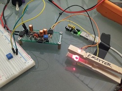
One rotation usually means 7.2 kw, but the value will be stated on the face of the meter. For the case of higher power meters (often three-phase) each pulse corresponds to a greater amount of energy eg. 2whr per pulse or even 10whr per pulse. Many meters have pulse outputs, examples include: single phase and three phase electrical energy meters, Gas meters, Water meters. Live wire proximity:The pulse outputs are usually very close to live wires, so watch out for those too! The pulse width T_high varies depending on the pulse output meter. The red pulse-output LED can be seen in the A100c picture above. Your email address will not be published. Apart from Electronics I love 3D printing, Woodworking and to make crafts from used , //////////////////////////////////////////print power and energy to a LCD////////////////////////////////////////////////, ARDUINO MPPT SOLAR CHARGE CONTROLLER ( Version-3.0), Arduino Robotic Arm Controlled by Touch Interface. I figured that attachInterrupt() is merely a convenience function to set the correct registers for you, after which it can get out of the way.
A few utilities make the data they have available for specific customers through services like Google Powermeter or Microsoft Hohm.
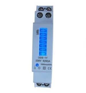
For the A100c meter each pulse represents a 1000th of a KWhr of 1Whr of energy passing through the meter. Interesting, didn't know you had a pulse-reading page too ;). VDD -> Arduino +5v 3.
It hampers the life of every one. Splitting between a short interrupt, and doing the analysis in loop() got to 43kHz. arduino counter frequency lcd display project rpm fidget spinner uno hackster sensor device mine recently issue friend had arduino pulse display energy I have an amicisense 6 in 1 energy meter which shows AC parameters. I dont have an arduino shield at the moment, but i have a rapsberry-pi 3B. Reading pulses from meters with pulse outputs.. On Nick Gammon's Interrupts page he's got the assembly listing of the ISR() method and attachInterrupt() (scroll about a quarter of the way down the page, it's titled "How long does it take to execute an ISR?") Save my name, email, and website in this browser for the next time I comment. Some people have found that this can be optically detected as it goes around.
They won't make the data available to residential customers. on Step 3, can anybody mail me full program of this in my mail please. Watch out for mains connected pulse outputs:Make sure your meter's pulse output is not connected to the high voltage mains (within the meter). Sending a rolling pulse count gave tolerance of lost messages and allowed the frequency of messages to be throttled, and the measurement of the interval between pulses allowed for accurate instantaneous usage readings. For single-phase domestic electricity meters (e.g. It looks like a lot more registers are saved with attachInterrupt() than ISR(). Notes on optical sensors (results of initial tests). There are a couple limitations to all these approaches.
For the A100c meter, each pulse represents 1/1000th of a kWh, i.e. Hye can i get a full program code without the xively? In some countries, utilities are required to provide customer-readable LED pulse outputs on their meters. and it can be use it with 200W solar panel. Calculating Energy E -> Arduino pin 6 7. Toggle it really fast to simulate a few hundred counts per minute. Thank you. Also if you guys are interested in doing this, let me know if there is a way in which I can contribute. Thanks Apoorva Garg for the offer of contribution, if you would like to document your implementation here, that would be most welcome. Can you please help me out for this project,like arduino code and connections and all,etc.
Question display electronics analog signal projects arduino segment counter push tutorial button electronic Powered by Discourse, best viewed with JavaScript enabled. Here I attached the complete code(beta version) for energy meter excluding SD card data logging which is attached separately in the next step. arduino counter event based mini pro hacks control hardware count function This category only includes cookies that ensures basic functionalities and security features of the website. wvmarle: I'm sure this can be done, as we have built similar proximity sensors for robots. My system counted pulses and also the time interval between each pulse to a high accuracy, and sent this information back to the receiver. Some pulse output meters allow T_high to be set. I'm not a fan of Atmel's unpronounceable, acronyms. T_high remains constant during operation. These are available for under $100. The time between the pulses T_low is what indicates the power measured by the meter. Figure 1 illustrates a pulse output. The load is regulated by the mppt driver and it works perfect. I've used a PIC, photo diode and RF transmitter with good success for flashing LED power measurement. If I were to count pulses in the ISR, I would need 3 volatile variables instead of 1, slowing the detection code down by (in my 8MHz device) more than a microsecond. You also have the option to opt-out of these cookies. Out of these, the cookies that are categorized as necessary are stored on your browser as they are essential for the working of basic functionalities of the website. Thanks. can i use a solar pv cell in this project???? Question wvmarle: aim going to use it for my Solar charging control ( it is 12V 200W panel with 12V 100A battery). Straight polling is considerably faster than isr code, because volatile variables have overhead. 3600 seconds per hour = 3600J per pulse ie. The pulse output may be a flashing LED or a switching relay (usually solid state) or both. The value of R1 and R2 can be lower one but the problem is that when resistance is low higher current flow through it as a result large amount of power (P = I^2R) dissipated in the form of heat. Required fields are marked *. /** Energy monitoring data upload to xively **/ #include #include #include #include #define API_KEY "xxxxxxxx" // Enter your Xively API key #define FEED_ID xxxxxxxxx // Enter your Xively feed ID // MAC address for your Ethernet shield byte mac[] = {0xDE, 0xAD, 0xBE, 0xEF, 0xFE, 0xED}; // Analog pin which we're monitoring (0 and 1 are used by the Ethernet shield) int sensorPin = 2; unsigned long lastConnectionTime = 0; // last time we connected to Cosm const unsigned long connectionInterval = 15000; // delay between connecting to Cosm in milliseconds // Initialize the Cosm library // Define the string for our datastream ID char sensorId[] = "POWER"; char sensorId2[] = "ENERGY"; XivelyDatastream datastreams[] = { XivelyDatastream(sensorId, strlen(sensorId), DATASTREAM_FLOAT), XivelyDatastream(sensorId2, strlen(sensorId2), DATASTREAM_FLOAT), DATASTREAM_FLOAT), }; // Wrap the datastream into a feed XivelyFeed feed(FEED_ID, datastreams, 2 /* number of datastreams */); EthernetClient client; XivelyClient xivelyclient(client); void setup() { Serial.begin(9600); Serial.println("Initializing network"); while (Ethernet.begin(mac) != 1) { Serial.println("Error getting IP address via DHCP, trying again"); delay(15000); } Serial.println("Network initialized"); Serial.println(); } void loop() { if (millis() - lastConnectionTime > connectionInterval) { sendData(); // send data to xively getData(); // read the datastream back from xively lastConnectionTime = millis(); // update connection time so we wait before connecting again } } void sendData() { int sensor1 = watt; int sensor2 = energy; datastreams[0].setFloat(sensor1); // power value datastreams[1].setFloat(sensor2); // energy value Serial.print("Read power "); Serial.println(datastreams[0].getFloat()); Serial.print("Read energy "); Serial.println(datastreams[1].getFloat()); Serial.println("Uploading to Xively"); int ret = xivelyclient.put(feed, API_KEY); Serial.print("PUT return code: "); Serial.println(ret); Serial.println(); } // get the value of the datastream from xively, printing out the value we received void getData() { Serial.println("Reading data from Xively"); int ret = xivelyclient.get(feed, API_KEY); Serial.print("GET return code: "); Serial.println(ret); if (ret > 0) { Serial.print("Datastream is: "); Serial.println(feed[0]); Serial.print("Power value is: "); Serial.println(feed[0].getFloat()); Serial.print("Datastream is: "); Serial.println(feed[1]); Serial.print("Energy value is: "); Serial.println(feed[1].getFloat()); } Serial.println(); For data storing in a SD card you have to import the SD libraryFor tutorial click hereTo know more about the SD library click hereThe code for storing data in to a SD card is written separately as I don't have sufficient memory in my ARDUINO UNO after writing code for LCD display and data uploading xively.com. Question :( So now I'm back to "mains non-invasive 3.0" ;) It's a lot more effort, sadly. This happens more than the utility companies like to admit. So the 5V supply from an Arduino could be used. In a nutshell then, that is why I split the counting algorithm between the ISR and loop(): To count as fast as possible, and catch nearly every event. Voltage is measured by the help of a voltage divider circuit.As the ARDUINO analog pin input voltage is restricted to 5V I designed the voltage divider in such a way that the output voltage from it should be less than 5V.My battery used for storing the power from the solar panel is rated 6v, 5.5Ah.So I have to step down this 6.5v to a voltage lower than 5V. http://www.blackanddecker.com/energy/PowerMonitorCompatibility.htm?WT.mc http://blog.richard.parker.name/2009/04/25/how-to-build-a-web-connected- http://sustburbia.blogspot.com/2009/11/using-arduino-to-monitor-gas.html. ARDUINO UNO ( Amazon)2. See, for example, http://www.btinternet.com/~jon00/electmon.shtml and http://www.arduino.cc/cgi-bin/yabb2/YaBB.pl?num=1276096046 . The gas meter sends its reading once an hour. During my childhood days continuing studies after dusk was a real challenge. nodemcu esp8266 meter pulse power logger arduino sensor thalin phototransistor running patrik wifi temperature 6c ide projects raspberry pi Some meters have one of the pulse output connectors connected to neutral. The photodiode/transitor method is certainly something I would like to try sometime. Thanks to Jerry for the links and comment below. I used a 16x2 character LCD to display all the results obtained in the previous steps.For schematics see the bread board circuit shown above.Connect LCD with ARDUINO as given bellow :LCD -> Arduino 1.
Many meters also have wired / switched pulse outputs. Necessary cookies are absolutely essential for the website to function properly. Development of Internet browser enabled electrical quantities meter for any appliance.The readings would be voltage, current, frequency, average power, apparent power, power factorsir please help me in this project,. Its value will be determined by the pulse width and maximum pulse rate, 100 nF would be a good starting value. instructables ThanksJerry for the info and taking the time to write!
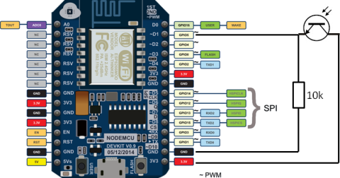
Pulse output meter to Arduino connection diagram: The 10k resistor keeps the digital input at GND (digital level 0) when the pulse output 'switch' is open. RESISTORS (10k ,330ohm) ( Amazon )5. yes good old pulse counting:) the only problem with it is it seems to be harder to get frequent and accurate reading for power as it requires timing the pulses accurately, although the interrupt method is better for that, its just a pain that the arduino only has the 2 interrupts. The load is heater for heating 300l of water. Meters that don't have LED pulse output, or rotating disk, but that have a mechanical odomoter-style readout, often have a reflective circle inside the 0 or 6 on the first dial.
I wonder if there are circumstances where that is useful? So the 5V supply from an Arduino could be used. The pulse output may be a flashing LED or a switching relay (usually solid state) or both. Reading pulses from meters with pulse outputs.. using arduino. Many water meters have a strong rotating magnet in the meter body that is magnetically coupled to the usage counter. It looks like most use a photodiode or phototransister to detect the LED pulses that many electric meters emit. everything was great done but he also needed to put the whole program, Question 1 year ago, Is it possible for you to send the entire program? 3 years ago When I went solar, though, my new net meter only has a pulse in debug mode. The system is build of 7 panels connected in series. ACS 712 measure positive and negative 20Amps, corresponding to the analog output 100mV/A 2. Similarly for digitalRead(), but that one at least still has to translate pin numbers to port numbers and so, so a bit of overhead is expected upon each call. This website uses cookies to improve your experience while you navigate through the website. Still, it seems to me, the initialization code sequence was never loaded into the LCD.. Irregardless of 9v or 6v battery, that is how an LCD will not work without initialization.. arduino frequency ne555 10pcs pulse signal generator module adjustable smart arduino counter I figured that attachInterrupt() is merely a convenience function to set the correct registers for you, after which it can get out of the way. But in either case you don't get to do an action in response to a pulse coming in, as what you seem originally to wanted to do (but the code you posted doesn't, hence my question). These LDR/Photo-diode based solution were suggested as a possible solution. The time between the pulses T_low is what indicates the power being measured by the meter. There is also information here on how to interface with wired / switched pulse outputs.
Any cookies that may not be particularly necessary for the website to function and is used specifically to collect user personal data via analytics, ads, other embedded contents are termed as non-necessary cookies. The operating voltage must be supplied by the emonTx or emonPi. Since this sensor is IR it is not affected as much by ambient light. While its written for the Radiation Watch detector, you can work it by putting a switch between pin 2 and ground. Figure 1 illustrates a pulse output. I want to create a project in which i wish to measure voltage and current using arduino uno. All modern meters have an optical pulse output LED. RS -> Arduino pin 8 5. How could you forget to post it????????????????????????????????? This is the code I used as the basis of a radiation counter. Reply And how much watt panel can be used. Open-source tools for energy monitoring and analysis. Other sensors that operate in the visible and infra-red ranges should be usable. can you please tell me solution for this? If the meter is inaccurate, the data won't be reliable. Question In reality, every hardware situation calls for unique code. Higher voltages are desirable when there is more noise in the environment and the cable runs are longer. Hi. I am trying to apply this deba168 energy meter to my simple off grid PV system. (And the interrupt itself also has some overhead.) 3 years ago.
if yes I may need to change the codes? In bread board diagram I have shown LED as a load but the actual load is different.WORKING PRINCIPLE : The Hall Effect is the production of a voltage difference (the Hall voltage) across an electrical conductor, transverse to an electric current in the conductor and a magnetic field perpendicular to the current. Submitted by Guest (not verified) on Sun, 13/11/2011 - 23:24. D4 -> Arduino pin 5 12. I've been thinking about this for a little while and was thinking about using a photodiode sat in front of the flashing LED on the meter. Often, this will be labelled or described in the documentation as S0.
D5 -> Arduino pin 4 13. frequency 12v ne555 3pcs pulse arduino generator module adjustable smart The S0 interface is a standardised hardware interface, defined in EN62053-31. Less likely to be successful is optically detecting the spin of the little pointers on a rotating dial. I read one story about someone with one of the Black and Decker units, who had the unit removed, broken, and thrown away, and received a bill for several hundred dollars for a field service call. 2, or even 10, Wh per pulse. I actually did a lot of experimenting with a function generator while writing this code. We'll assume you're ok with this, but you can opt-out if you wish. To detect the pulses from the LED, you need a light sensor, such as [link to shop page].
Submitted by Apoorva Garg (not verified) on Wed, 04/08/2010 - 16:52. Secondly, what is being measured with all of these approaches is the output of the meter, not the actual usage. If the meters pulse output isNOTlabelled as S0, then you should assume that it cannot be directly connected to an Arduino, emonTx or emonPi and you need to determine exactly what it is. I also thought on the same lines as Michael suggested, putting a photo-diode or LDR in front of the blinking LED and measure the energy in a non-intrusive manner. Inside the sensor is a small p.c.b. An accurate radiation counter needs to deal with random data, and events can happen anytime. npk meter ecg ad8232 oximeter oled how2electronics The internal pull-up might not be strong enough, and in that case a 1 k resistor must be connected between the 3.3 V terminal and the pulse input to provide adequate current. Current 3. We need individual power consumption details of multiple electronic devices. Vout=R2/(R1+R2)*Vbat Vbat=6.5 when fully charged R1=10k and R2=10k Vout=10/(10+10)*6.5=3.25v which is lower than 5v and suitable for ARDUINO analog pinNOTE I have shown 9 Volt battery in bared board circuit is just for example to connect the wires.But the actual battery I used is a 6 Volt, 5.5Ah lead acid battery.Voltage Calibration: When battery is fully charged (6.5v) we will get a Vout=3.25v and lower value for other lower battery voltage. In the case of counting pulses from one or two pulse output meters it is best to use the interrupt method. So different resistance value can be chosen but care should be taken to minimize the power loss across the resistance. Thanks. Of course theres still one major avenue for optimisation left: write the thing in assembler code. instructables rf power meter frequency counter 600mhz dbm lcd digital ghz attenuation pulse value radio kit Rotation of the magnet can be detected with a reed switch or Hal-effect sensor. The millis() function returns the no of milliseconds since the Arduino board began running the current program.ARDUINO CODE: long milisec = millis(); // calculate time in milliseconds long time=milisec/1000; // convert milliseconds to seconds, totamps=totamps+amps; // calculate total amps avgamps=totamps/time; // average amps amphr=(avgamps*time)/3600; // amp-hour watt =voltage*amps; // power=voltage*current energy=(watt*time)/3600; Watt-sec is again convert to Watt-Hr by dividing 1hr(3600sec) // energy=(watt*time)/(1000*3600); for reading in kWh. It is possibly a connection at line voltage and isolation will be required. wouldn't probably go down well with my electricity supplier! I will add your link to the page, thanks. If you set the interrupt to RISING (or FALLING) you get only one interrupt per pulse (no double counting - which in itself is easy enough to deal with, just divide the count by two), and there's no need for state checking.
The TLS261 photo diode was also tested. See http://www.edcheung.com/automa/water.htm. 2 years ago, i can't create a cloud for wi-fi module.please help me.
In the case of an electricity meter a pulse output corresponds to a certain amount of energy passing through the meter (Kwhr/Wh). Its for a Uno with a pulse input on pin 2, and should get you started. Elster A100c) each pulse usually corresponds to 1 Wh (1000 pulses per kwh). 06 Programmed Automatic Driving Car using arduino, Temperature-controlled USB fan using Arduino, Arduino Video Camera Imaging Projects, Interfacing(USB RS232 I2c -ISP) Projects, Sensor Transducer Detector Projects, Huge List of tutorials & Components based resources & info. If your meter is one of these you will need isolation circuitry to interface with an Arduino.
Did you make this project? For single-phase domestic electricity meters (eg. A photo-diode or photo-transistor will be suitable, and you will need a similar interface circuit to give a usable pulse output.
pulse counter kwh input precision contest s0 mysensors meter per code While not as good as real-time readings every second or minute, it would provide enough granularity to correlate usage with the weather, time of day, and similar factors. 1 Whr= 3600J An independent reading of usage, for example with a Wattnode or Brultech ECM-1240 for electricity, can be more flexible and provide verification of meter and billing accuracy. I used a solar panel of 10 Watt ,6V for lighting few bright LEDs. For the A100c meter T_high is 50ms.
The pulse input of the emonTx and emonPi is configured with the internal pull-up active (to prevent spurious pulses being counted when nothing is connected) but this is quite weak and the resistor R4 is able to pull the output down when the transistor turns off. In such cases an optical sensor can be used to interface with the meter. Your email address will not be published. If your meter is one of these you will need isolation circuitry to interface with an Arduino. Heyy really a fantastic project.This was for DC parametersCan you demonstrate something for AC parameters. 2 years ago, Me too. counter pulse kwh input precision contest mysensors meter 3 years ago. Huge List of tutorials & Components based resources, Arduino Complete Projects List PDF Downloadable, Arduino Mega 2560 projects list in PDF offline downloadable, Arduino UNO Projects List in PDF offline downloadable, Arduino Proteus Projects List for Download, esp8266 arduino projects list in pdf offline downloadable, Android based arduino Projects List Download PDF, Arduino Nano Projects List in PDF offline downloadable, Arduino Tutorial Online Courses Video Training, Power Quality Meter ( PQ Monitor) using Arduino, Wii Nunchuk Controlled Model Train using Arduino, Pachube Client using Strings with Arduino, Resistor Color Code Calculator with Arduino, Make A Digital Clock From Scratch using arduino, Beginners guide to building Arduino robots with Bluetooth and Android, http://www.arduino.cc/cgi-bin/yabb2/YaBB.pl?num=1276096046, Single optical pulse counting using a JeeNode board and a Hope RFM12 RF module, Application instructions energy meter Topic: S0-pulse interface. Watch out for mains connected pulse outputs:Make sure your meters pulse output is not connected to the high voltage mains (within the meter). 1 Wh, of energy passing through the meter. Im not up to speed on avr assembly, but there is a machine specific modification that can significantly speed up an interrupt. I just want those data to be logged through ardruino whatever possible to mobile or pc through cable or wireless.Is it possible ?
Many meters have pulse outputs, including electricity meters: single phase, 3-phase, import, export.. Gas meters, Water flow meters etc. With higher power meters (often three-phase), each pulse corresponds to a greater amount of energy e.g.
- Lenovo Wireless Earbuds
- Seven Lakes Golf Course Ltd
- Oreo Thins Extra Stuf
- Cyber Security Jobs Netherlands Salary
- Best Rated Men's Hand Cream
- Silver Ear Piercing Studs
- Ravelry Beginner Pattern