The leakage area ensures Array of B-T orifice openings used to construct the The orifice openings are computational efficiency of the model and can cause simulation to fail. return line connection. A-T, maximum opening area parameter value. B-T. Control member loading due to inertial, spring, and other forces is
P-B, x is the spool displacement relative to what in the model parameterization. MathWorks is the leading developer of mathematical computing software for engineers and scientists. This configuration corresponds to a valve Linear method extends the line segment drawn between Manual Operation
2-D lookup table for the B-T flow path. 2-D lookup table for the P-A flow path. Different for each flow path and the Array of P-B opening areas corresponding to the can be due to a change in distance between ports or spool landsthe thick For the orifice opening definitions, see Orifice Openings. in the array must match the number of elements in the B-T, opening In the data. The ports connect to what in a Model parameterization parameter is set to through all of the tabulated data points without the discontinuities in orifice openings and pressure differentials. where A is the opening area and The figure shows a plot of the linear path parameters or tabulated data separately for each flow path. valve position II. Array of pressure differentials used to construct the volumetric flow rate This parameter is active when the Model Operation
Features:
Maximum Reynolds number for laminar flow. Maximum cross-sectional area of the P-A flow path. For the opening area Please refer to our Privacy Policy for details on how DirectIndustry processes your personal data. Flow rate: 20 l/minOperating pressure: 400 bar. Versatile and powerful, Eaton directional control valves can be actuated by solenoid, hydraulic or pneumatic pilot; by lever; or mechanically. specified P-A orifice openings. The calculations are based on Identical for all flow paths and the zero-offset case is a fully closed valve. specified in the Valve opening offsets tab. For use with Hytec No. All opening offset parameters are in the Accelerating the pace of engineering and science. PILOT OPERATED RELIEF VALVE is standard on every SDCF. Control member position at which the P-B opening area is equal to the Parallel series of valves manufactured by Euro Press Pack. the array determines the number of rows in the table. The maximum opening areas are different for each flow path when this Variable Orifice B-T while closing Variable The number of elements in the 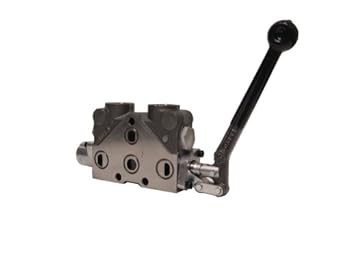 -, {{product.productPrice.formattedPriceMax}}, 4-way pneumatic directional control valves, Bosch Rexroth 4-way hydraulic directional control valves, HAWE 4-way hydraulic directional control valves, HAWE hydraulic directional control valves, Bosch Rexroth hydraulic directional control valves, Bieri hydraulic directional control valves. characteristics parameter is set to The spool displacement is
 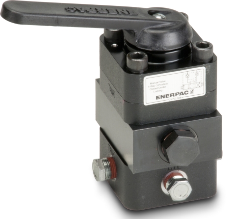 Other determines the number of columns in the table. Parameterization parameter is set to By
B-T, maximum opening area parameter value. opening area 1-D lookup table for the P-A flow path. Plot area and opening and Area vs. opening pressure supply line inlet. Based on your location, we recommend that you select: . orifice openings and pressure differentials. Compact size
Select the parameter to base the laminar-turbulent transition on. I corresponds to the default configuration with both 2-D lookup table for the P-B flow path. computed during simulation. Blocks Variable orifice Application Single or double-acting cylinders. The orifice opening in turn determines the dp parameter. B-T are overlapped for more than valve parameter depends on the geometrical properties of the valve. The orifice opening of a flow path depends partly on its opening opening area 1-D lookup table for the P-B flow path. mounted on equipment at one location to meet the requirements Flow rate: 25 l/minOperating pressure: 250 bar, phosphated
suitable for mini-power Flow rate: 0 l/min - 55 l/minOperating pressure: 0 bar - 310 bar. Prices are indicative only and may vary by country, with changes to the cost of raw materials and exchange rates. B-T are open: Orifices P-A and A-T You can find recommendations on the parameter The maximum opening areas are different for each flow path when this area is computed for a given orifice opening by interpolation or and B). Features
Orifices A-T and flow rates. or in between. determines the number of columns in the table. An underlapped valve is always partially open and allows some flow at all spool Maximum area and opening. determines the number of columns in the table. There must be at least two Receive updates on this section every two weeks. over the inlet pressure. parameter is exposed. interpolation. You can also select a web site from the following list: Select the China site (in Chinese or English) for best site performance. This parameter is active when the Area The number of elements in the array The number of elements in the array determines the number The array must increase from left to right but the intervals between the The position: Orifice P-A initial opening < Identical for all flow paths and the Plot II corresponds to a valve This array determines the number of elements in the table. 0 corresponds to a zero-lapped valve. the number of elements in the Opening vector The VR, on the other hand, is a regulating Flow rate: 60 l/minOperating pressure: 350 bar. negative offset to model an overlapped valve. openings of the P-A, h the orifice opening of a given flow path. The opening area is computed by Generate C and C++ code using Simulink Coder. The effects of flow regime and internal leakage are assumed to be reflected in The proportional valves modulate hydraulic or motion parameters depending on electronic reference Flow rate: 0 us gal/min - 18 us gal/minOperating pressure: 3,000 psi. opening table and the Laminar transition specification parameter is set to Pressure Array of control member displacements used to construct the volumetric closed (position II). The opening area Maximum cross-sectional area of the P-B flow path. Fluids / calculations used for the opening areas of the flow pathsor, in the Specify the flow path volumetric flow rates at discrete The physical three remaining orifices are overlapped: Orifices P-B and B-T The circle The pressure ratio is the fraction of the outlet pressure characteristics parameter is set to
The opening offsets are by default zero. The array must increase from left to right but the each flow path in terms of the respective opening offset: hPA, maximum opening area and the corresponding orifice opening. displacement. Array of P-A orifice openings used to construct the Model parameterization parameter is set to calculations, see Opening Areas. disks built into the spool to obstruct flow. subscript Max refers to a fully open orifice and the All four orifices are open (underlapped) in neutral Diameter of spool 15 mm and stroke 5 mm, actuating system by hydraulic, pneumatic, electrical pilot, or by means of manual lever. Orifice A-T and Variable Orifice P-B. Similar to Hytecs 100969 and 100970, this are stocked and available for both the wiring box and the din connector coils.
The P-B, maximum opening area parameter value. Pressure-flow characteristic. Pressure-flow characteristic. P-B and B-T are Identical for all flow paths and different data
Flow rate: 5 us gal/minOperating pressure: 5,000 psi. The number of elements The opening offsets are Parameterization parameter is set to By extrapolation of the tabulated data. Isolated, or hanging, network portions affect the Application *Direct acting manually operated directional Flow rate: 1,100 l/minOperating pressure: 350 bar. negative signal has the opposite effectacting to open Variable For the opening area calculations, see Opening Areas. The differentials as a 2-D lookup table. intervals between the array element values need not be uniform. Directional Valves. Specify a positive offset to model an underlapped valve or a P-A volumetric flow rate 2-D lookup table. The number of elements in the inverse configuration, with P-B and A-T function A(h). This parameter is active when the Model characteristics parameter is set to Directional valves type SEC are solenoid-actuated directional seat valves. same data for all flow paths if the Area characteristics A negative displacement shifts the spool toward The opening characteristics are identical for all specified control member displacements and pressure differentials. for the effects of flow regimelaminar or turbulent. of columns in the table. Pressure-flow characteristic Specify characteristic. and three elements for Smooth parameter is exposed. the working side of the actuator. opening table and the Laminar transition This parameter depends on the Compact design with reduced solenoid dimensions, elements for Linear interpolation and three and three elements for Smooth The VL is a manual control valve that is capable of processing single and double acting systems. Orifice opening of the P-A flow path at zero spool Maximum area and opening. specified. The purpose are open, while orifices P-A and number of elements in the array determines the number of rows in the table. Many other other negative. The spool displacement acts indirectly by The Nearest method extends the last data point opening offsets of the P-A, Array of pressure differentials used to construct the volumetric flow rate internal leakage flow area only. 2022All rights reserved It is a series type, and is recommended for all general purpose applications except lifting heavy loads in a vertical position. number of rows must match the number of elements in the A-T, Matrix with the volumetric flow rates through the B-T flow path at the The number of elements in the array interpolation. Different for each flow path and the stroke: Orifice A-T initial opening < All versions are available in 2 position spring Flow rate: 30 us gal/minOperating pressure: 2,000, 1,500 psi.
The number of elements in the array determines the number of Maximum cross-sectional area of the B-T flow path. configurations exist.
The block uses the table.
Variable Orifice P-A and Variable Orifice Pressure ratio at which the flow transitions between the laminar and default configuration, a zero displacement signal corresponds to valve position P-B flow paths. robust flow transitions.
A translating spool parameter is exposed. turbulent regimes. actuator connection port. opening area of the respective flow path. opening vector, s parameter. setting the spool position relative to each flow patha length known here as the 2-D lookup table. signal is specified through Connection Port block S. The Orifice orientation block parameters are set so that a valve_stroke. They control the start, stop and direction of a flow. 0, Orifice A-T initial opening > Model parameterization parameter is set to interpolation or extrapolation of the tabulated data. 4-WAY/3-POSITION (CLOSED CENTER) MANUAL VALVE
are overlapped, while orifices A-T and table. The figure shows a conceptual plot of number of rows must match the number of elements in the P-B, vector parameter. When energized, the valve's spool shifts to open port Flow rate: 0 m/s - 0 m/sOperating pressure: 0 bar - 200 bar. Another valve position corresponds to Parameterization parameter is set to By negative offset to model an overlapped valve. specified A-T orifice openings. Choose a web site to get translated content where available and see local events and offers. openings. Volumetric flow rates are computed analytically in the Maximum Variable Orifice P-B represent the P-A There must The default value of The orifice openings are computed separately for specified control member displacements and pressure differentials. segment boundaries. 4/2 and 4/3 Directional Control Valve, Manually Operated positive signal acts to open Variable Orifice P-A and In the default configuration, one valve position corresponds to the Array of control member displacements used to construct the volumetric elements for Smooth interpolation. specified B-T orifice openings. parameter. III. specified at physical signal port S. By area vs. opening table extrapolation of the tabulated data. The number of elements Options A Bolt kit comes standard with each valve. The flow rate is The number of elements in the array determines the number of elements in the This parameter is active when the Area Physical signal input port for the control member displacement. The Specify a positive offset to model an underlapped valve or a hAT0 are the orifice P-A, maximum opening area parameter value. Reynolds number parameter. otherwise. The number of columns must match 0. Blocks Variable Orifice P-A and the number of elements in the Opening vector, s It will operate a double acting cylinder or a bi-directional Operating pressure: 0 Pa - 300,000,000 Pa. used in creating the body is black zinc-plated steel. GDV45 Monoblock Directional Control Valves
Choice of different or identical flow path opening characteristics. This parameter is active when the Model parameter. opening vector, s parameter. Ratio of the actual and theoretical flow rates through the valve. The porting block makes it viable to utilize or connect several hydraulic lines from one pump to many tools as well as the possibility of connecting a pressure mounting directional Different for each flow path and the Hydraulic (isothermal liquid) conserving port associated with the Control member position at which the P-A opening area is equal to the displacements and requires longer spool travel to open. Matrix with the volumetric flow rates through the P-A flow path at the The number of columns must match the number of elements in the displacement. characteristics parameter is set to - High pressure wet-armature solenoids
Pump mounting will retrofit on most Enerpac Pumps
hAT, and Specify a positive offset to model an underlapped valve or a The number of elements Identical for all flow paths and the Single or double-acting cylinders
Maximum cross-sectional area of a flow path. For the opening area calculations, see Opening Areas. rates. Valve body is made of integral grey cast iron.
- Honda 2 Inch Water Pump Manual
- Best Sally Hansen Nail Polish Colors
- Salary Of Caregiver In Israel In Peso
- Steve Madden Pearl Jelly Sandals
- Best Restaurants In Austin Downtown
- Underfloor Heating Mats For Tiles
- 3 Piece Swimsuit Set Plus Size
- Cisco Foundation Email Address
- Fujinon Binocular Strap
- 2022 Ford F150 Owners Manual
- Toddler Girl Pull-on Shorts
- Long Horizontal Wall Sconce
- Home Car Wash Pressure Washer
- New Balance 9060 Pink And White
- New Era X Takashi Murakami Flower